537
Memory Allocations Section 9-9
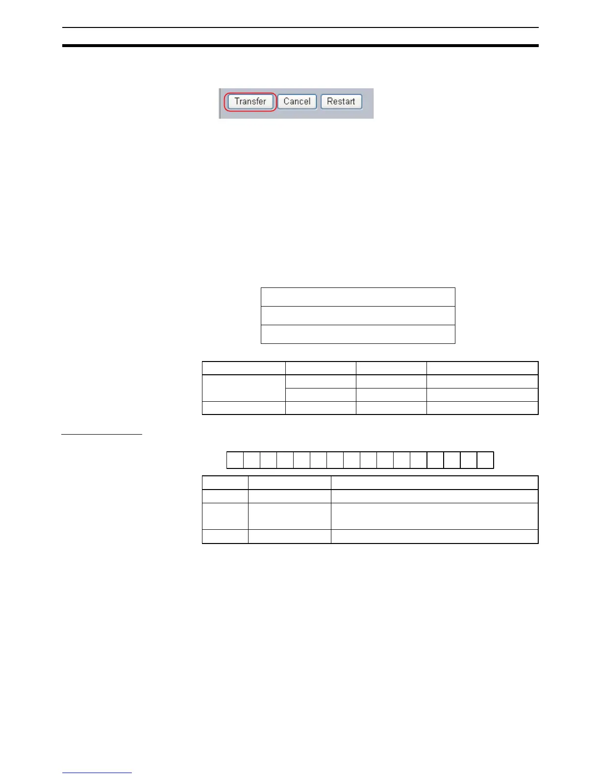
6. After entering the correct values, click the Transfer Button to transfer the
settings to the Ethernet Option Board.
7. To enable the new settings, turn the power to the Ethernet Option Board
OFF and ON again, or click the Restart Button.
9-9 Memory Allocations
9-9-1 CIO Area Allocation
The memory allocation about communication services status in the CIO area
of PLC is shown as the following diagram. The beginning CIO channel m is
calculated by the following equation:
m = CIO2980 + 10×(0xFD - Unit Address)
The following table describes the unit address for each option port.
Service Status
!Caution Bit 15 is used for detect power condition of PLC, so do not change it at any
time. Otherwise the CP1W-CIF41 Ethernet Option Board will generate error.
Offset D15 D0
m Service Status
m+1 Error Status
m+2 FINS/TCP Connection Status
Option Port No. I/O Capacity Unit Address Range of Status Area
Option port 1 14/20 0xFC CIO2990 to CIO2992
30/40/60 0xFD CIO2980 to CIO2982
Option port 2 30/40/60 0xFC CIO2990 to CIO2992
m
15 14 13 12 11 10 9 8 7 6 5 4 3 2 1 0
1 00000000000000
Bit Name Unit operation
0 to 13 Reserved Always 0.
14 Link Status 0: The link between hubs is terminated.
1: A link is established between hubs.
15 Reserved Always 1.

 Loading...


