53
Specifications Section 2-2
2-2-3 I/O Specifications for XA and X CPU Units
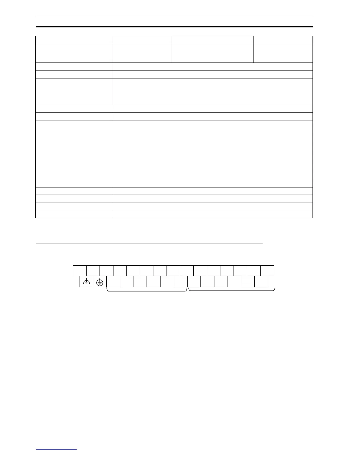
Relationship between Built-in Inputs and Terminal Block Arrangement
Terminal Block Arrangement
TR Area 16 bits: TR0 to TR15
HR Area 8,192 bits (512 words): H0.00 to H511.15 (words H0 to H511)
AR Area Read-only (Write-prohibited)
7,168 bits (448 words): A0.00 to A447.15 (words A0 to A447)
Read/Write
8,192 bits (512 words): A448.00 to A959.15 (words A448 to A959)
Timers 4,096 bits: T0 to T4095
Counters 4,096 bits: C0 to C4095
DM Area 32 Kwords: D0 to D32767
Note Initial data can be transferred to the CPU Unit's built-in flash memory using the
data memory initial data transfer function. A setting in the PLC Setup can be
used so that the data in flash memory is transferred to RAM at startup.
DM Area words for CJ-series Special I/O Units:
D20000 to D29599 (100 words × 96 Units)
DM Area words for CJ-series CPU Bus Units:
D30000 to D31599 (100 words × 16 Units)
DM fixed allocation words for Modbus-RTU Easy Master
D32200 to D32249 for Serial Port 1, D32300 to D32349 for Serial Port 2
Data Register Area 16 registers (16 bits): DR0 to DR15
Index Register Area 16 registers (16 bits): IR0 to IR15
Task Flag Area 32 flags (32 bits): TK0000 to TK0031
Trace Memory 4,000 words (500 samples for the trace data maximum of 31 bits and 6 words.)
Type X CPU Units XA CPU Units Y CPU Units
Model CP1H-X40DR-A
CP1H-X40DT-D
CP1H-X40DT1-D
CP1H-XA40DR-A
CP1H-XA40DT-D
CP1H-XA40DT1-D
CP1H-Y20DT-D
L1 L2/N COM 01 03 05 07 09 11 01 03 05 07 09 11
00 02 04 06 08 10 00 02 04 06 08 10
Upper Terminal Block (Example: AC Power Supply Models)
Inputs (CIO 0) Outputs (CIO 1)
Normal in

 Loading...


