47
Part Names and Functions Section 2-1
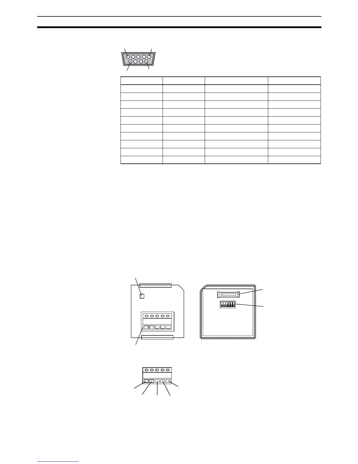
RS-232C Connector
2-1-3 CP1W-CIF11/CIF12 RS-422A/485 Option Boards
RS-422A/485 Option Boards can be mounted to Option Board slots 1 or 2 on
the CPU Unit.
When mounting an Option Board, first remove the slot cover. Grasp both of
the cover's up/down lock levers at the same time to unlock the cover, and then
pull the cover out.
Then to mount the Option Board, check the alignment and firmly press it in
until it snaps into place.
!Caution Always turn OFF the power supply to the PLC before mounting or removing
an Option Board.
RS-422A/485 Terminal Block
Pin Abbr. Signal name Signal direction
1 FG Frame Ground ---
2 SD (TXD) Send Data Output
3 RD (RXD) Receive Data Input
4 RS (RTS) Request to Send Output
5 CS (CTS) Clear to Send Input
6 5V Power Supply ---
7 DR (DSR) Data Set Retry Input
8 ER (DTR) Equipment Ready Output
9 SG (0V) Signal Ground ---
Connector hood FG Frame Ground ---
5
6
1
9
COMM
RDA− RDB+ SDA− SDB+ FG
Front Back
(1) Communications Status Indicator

 Loading...


