42
Part Names and Functions Section 2-1
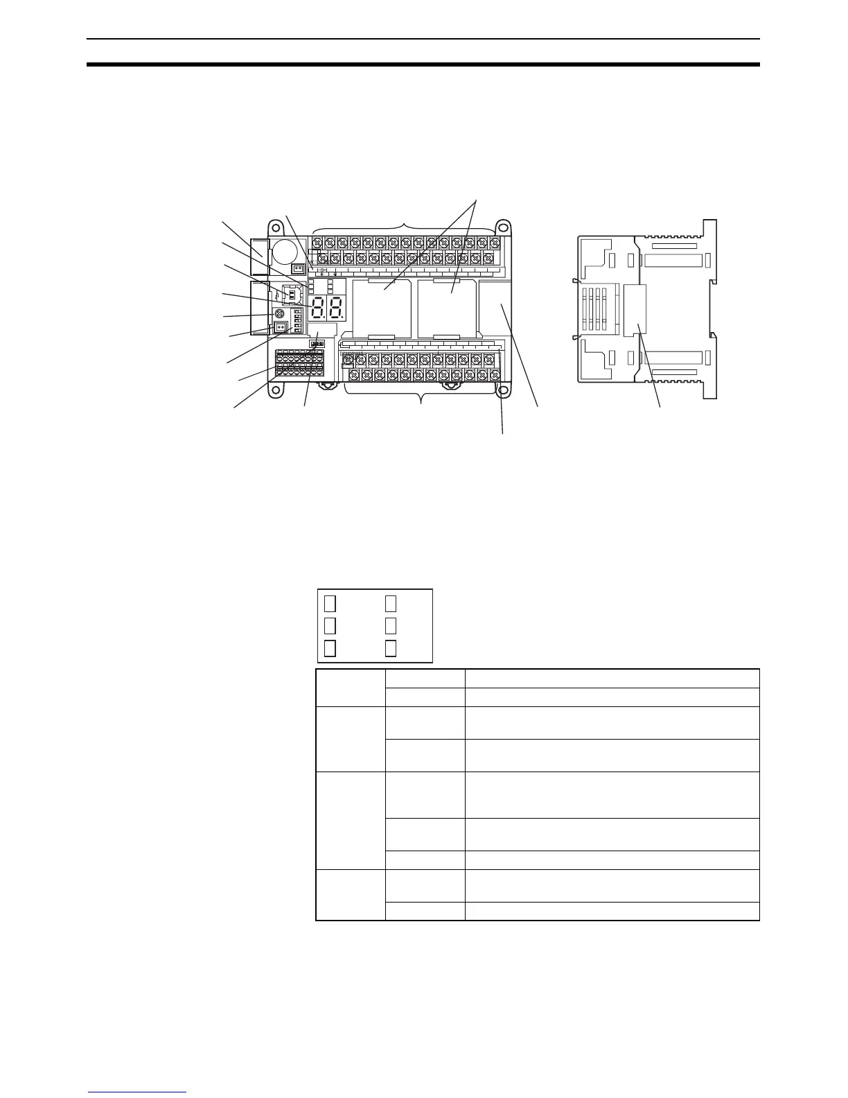
2-1 Part Names and Functions
2-1-1 CP1H CPU Units
(1) Battery Cover
Covers the location where the battery is stored.
(2) Operation Indicators
Show CP1H operation status.
POWER
ERR/ALM
BKUP
100CH 101CH
1CH
EXP
L1 L2/N COM 01 03 05 07 09 11 01 03 05 07 09 11
00 02 04 06 08 10 00 02 04 06 08
10
00 01 02 03 04 06 00 01 03 04 06
COM COM COM COM 05 07 COM 02 COM 05
07
IN
OUT
Front Back
(1) Battery cover
(2) Operation indicators
(3) Peripheral USB port
(4) 7-segment display
(5) Analog adjuster
(6) External analog settings
input connector
(7) DIP switch
(8) Built-in analog I/O terminal
block and terminal block
base (See note 1.)
(9) Built-in analog input switch
(See note 1.)
(11) Power supply, ground,
and input terminal block
(12) Option Board slots
(13) Input indicators
(14) Expansion I/O
Unit connector
(15) Output indicators
(10) Memory
Cassette slot
(16) External 24-VDC
(See note 2.)
and output terminal
block
(17) Connector for CJ Unit
Adapter
Note 1: XA CPU Units only.
Note 2: CPU Units with AC Power Supply only.
1
2
3
4
ON
POWER
(Green)
Lit Power is ON.
Not lit Power is OFF.
RUN
(Green)
Lit The CP1H is executing a program in either RUN or
MONITOR mode.
Not lit Operation is stopped in PROGRAM mode or due to
a fatal error.
ERR/ALM
(Red)
Lit A fatal error (including FALS execution) or a hard-
ware error (WDT error) has occurred. CP1H opera-
tion will stop and all outputs will be turned OFF.
Flashing A non-fatal error has occurred (including FAL execu-
tion). CP1H operation will continue.
Not lit Operation is normal.
INH
(Yellow)
Lit The Output OFF Bit (A500.15) has turned ON. All
outputs will be turned OFF.
Not lit Operation is normal.
POWER
ERR/ALM
BKUP
RUN
INH
PRPHL

 Loading...


