158
Data Link Area Section 4-4
4-4 Data Link Area
Data Link Area addresses range from CIO 1000 to CIO 1199
(bits CIO 1000.00 to CIO 1199.15). Words in the Link Area are used for data
links when LR is set as the data link area for Controller Link Networks. It is
also used for PLC Links. Words in the Link Area can be used in the program
when LR is not set as the data link area for Controller Link Networks and PLC
Links are not used.
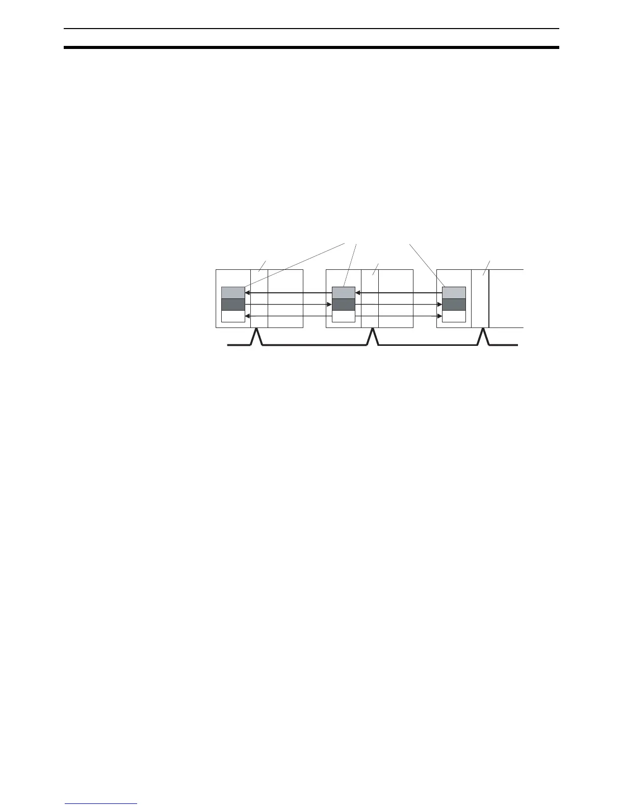
Data links can be generated automatically (using the same number of words
for each node) or manually. When a user defines the data links manually, any
number of words can be assigned to each node, and nodes can be made
receive-only or transmit-only. Refer to the Controller Link Units Operation
Manual (W309) for details.
Forcing Bit Status Bits in the Data Link Area can be force-set and force-reset.
Links to C200HX/HG/HE,
C200HS, and C200H PLCs
Link Area words CIO 1000 to CIO 1063 in CP1H CPU Units correspond to
Link Relay Area words LR 0 to LR 63 for data links created in
C200HX/HG/HE(-Z) PLCs. When converting C200HX/HG/HE(-Z), C200HS,
or C200H programs for use in CP1H CPU Units, change addresses LR 0
through LR 63 to Link Area addresses CIO 1000 through CIO 1063.
Link Area Initialization The contents of the Link Area will be cleared in the following cases:
1. When the operating mode is changed from PROGRAM mode to
RUN/MONITOR mode or vice-versa and the IOM Hold Bit is OFF
2. When the power is cycled
3. When the Data Link Area is cleared from the CX-Programmer
4. When PLC operation is stopped when a fatal error other than an
FALS(007) error occurs. (The contents of the Link Area will be retained if
FALS(007) is executed.)
Controller
Link Unit
CPU Unit
Linked words
Controller
Link Unit
CPU Unit
Controller
Link Unit
CPU Unit
Controller Link Network

 Loading...


