216
High-speed Counters Section 5-2
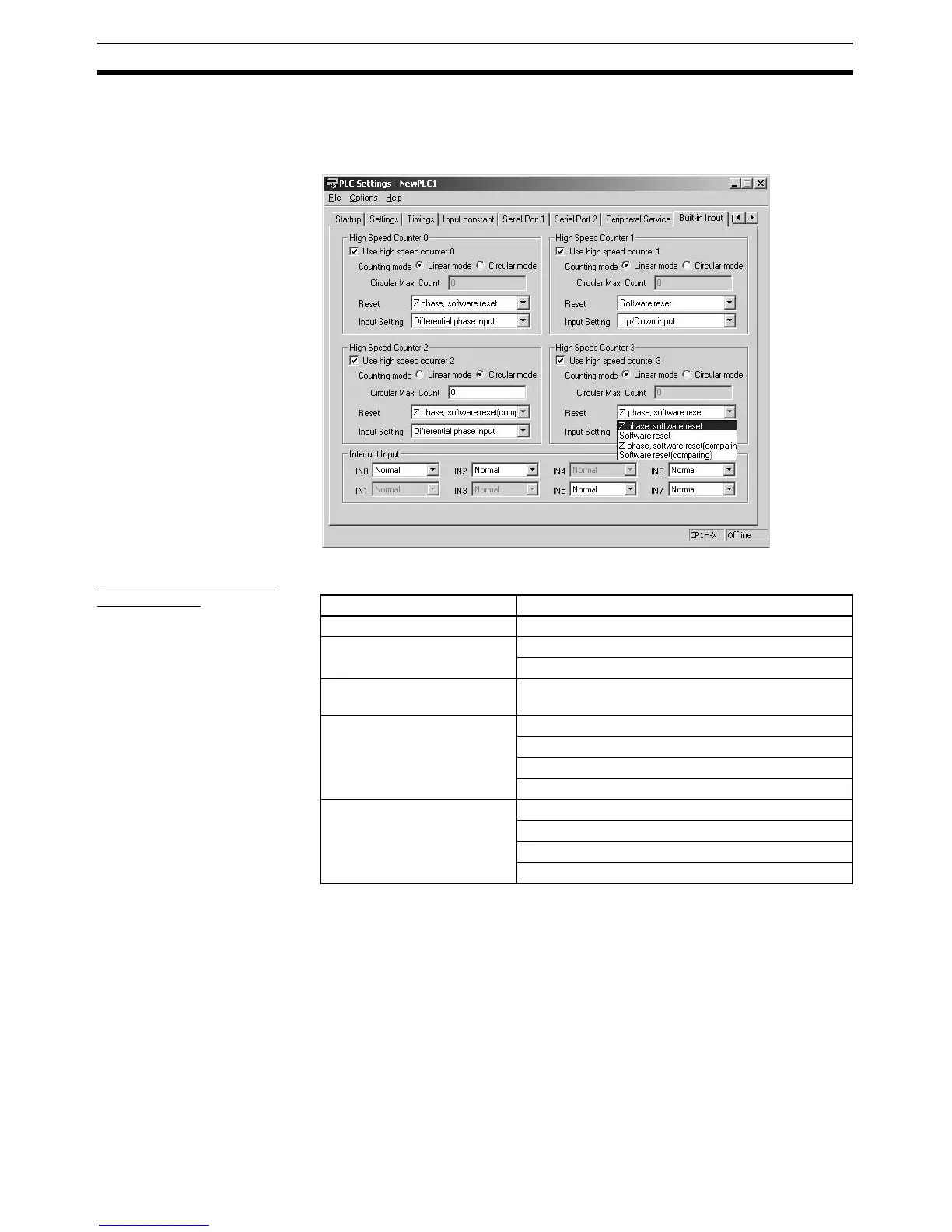
5-2-4 PLC Setup
The settings for high-speed counters 0 to 3 are located in the Built-in Input
Tab of the CX-Programmer’s PLC Settings Window.
Settings in the Built-
in Input Tab
5-2-5 High-speed Counter Terminal Allocation
The following diagrams show the input terminals that can be used for high-
speed counters in each CPU Unit.
Item Setting
Use high speed counter 0 to 3 Use counter
Counting mode Linear mode
Circular mode (ring mode)
Circular Max. Count
(max. ring count)
0 to 4,294,967,295 (0 to FFFF FFFF hex)
Reset method Phase Z and software reset
Software reset
Phase Z and software reset (continue comparing)
Software reset (continue comparing)
Input Setting Differential phase inputs (4x)
Pulse + direction inputs
Up/Down inputs
Increment pulse input

 Loading...


