58
Specifications Section 2-2
Output Specifications
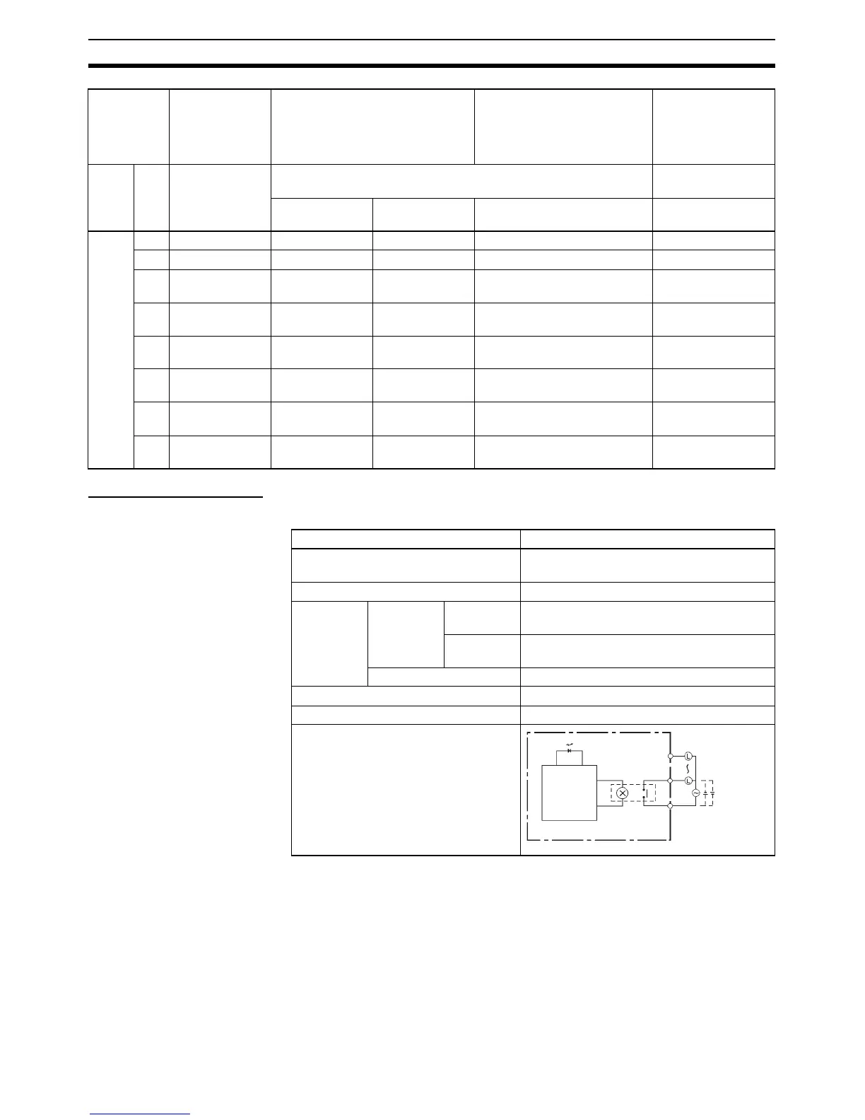
Relay Outputs
Under the worst conditions, the service life of output contacts is as shown
above. The service life of relays is as shown in the following diagram as a
guideline.
CIO
101
00 Normal output 8 --- --- --- PWM output 0
01 Normal output 9 --- --- --- PWM output 1
02 Normal output
10
--- --- Origin search 0 (Error counter
reset output)
---
03 Normal output
11
--- --- Origin search 1 (Error counter
reset output)
---
04 Normal output
12
--- --- Origin search 2 (Error counter
reset output)
---
05 Normal output
13
--- --- Origin search 3 (Error counter
reset output)
---
06 Normal output
14
--- --- --- ---
07 Normal output
15
--- --- --- ---
Output
terminal
block
When the
instructions to
the right are
not executed
When a pulse output instruction
(SPED, ACC, PLS2, or ORG) is
executed
When the origin search
function is set to be used in
the PLC Setup, and an
origin search is executed by
the ORG instruction
When the PWM
instruction is
executed
Word Bit Normal
outputs
Fixed duty ratio pulse output Variable duty ratio
pulse output
CW/CCW Pulse plus
direction
+ When the origin search
function is used
PWM output
Item Specification
Max. switching capacity 2 A, 250 VAC (cosφ = 1)
2 A, 24 VDC (4 A/common)
Min. switching capacity 10 mA, 5 VDC
Service life
of relay
Electrical Resistive
load
100,000 operations (24 VDC)
Inductive
load
48,000 operations (250 VAC, coφs = 0.4)
Mechanical 20,000,000 operations
ON delay 15 ms max.
OFF delay 15 ms max.
Circuit configuration
COM
OUT
OUT
Output LED
Internal
circuits
Maximum
250 VAC: 2 A
24 VDC: 2 A

 Loading...


