447
CompoBus/S I/O Link Units Section 7-6
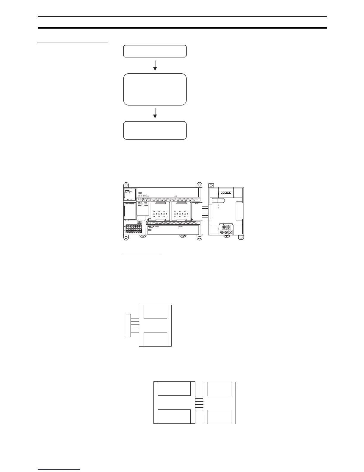
Operating Procedure
Connecting the
CompoBus/S I/O Link Unit
CompoBus/S I/O Link Units are connected to the CP1H CPU Unit. Up to
seven Units can be connected, including any other Expansion Units and
Expansion I/O Units that are also connected. The Units can be connected in
any order from the CPU Unit.
I/O Allocation
I/O words are allocated to the CompoBus/S I/O Link Unit in the same way as
to other Expansion Units and Expansion I/O Units, i.e., the next available input
and output words are allocated. As shown below, when “m” is the last allo-
cated input word and “n” is the last allocated output word, the CompoBus/S I/
O Link Unit is allocated “m+1” as its input word and “n+1” as its output word.
In the following example, a CompoBus/S I/O Link Unit is connected as the first
Unit after the CP1H CPU Unit.
Connect the Unit.
Determine the node
address of the
CompoBus/S I/O Link Unit
and set the DIP switch.
Wire the CompoBus/S
transmission path.
• Connect the CompoBus/S I/O Link Unit.
• The node number should be a unique number between
0 and 15.
• Use the DIP switch to set the CompoBus/S I/O Link
Unit fs node number, communications mode, and the
status of output data when a communications error
occurs.
• Connect the CompoBus/S I/O Link Unit to a
CompoBus/S transmission path.
CPU Unit
CompoBus/S I/O Link Unit
BD L NC( BS-) N C
BD H NC( BS+)
S
COMM
ERR
ON
12 3
4
5
6
No
.
SRT21
EXP
Word m+1
CompoBus/S I/O Link Uni

 Loading...


