127
Wiring Methods Section 3-5
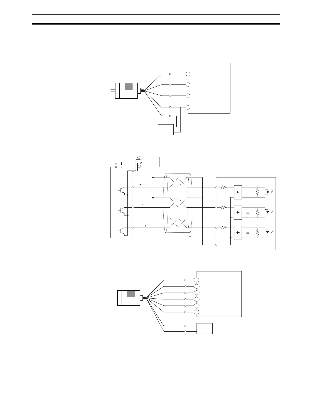
3-5-3 Pulse Input Connection Examples
For a 24-VDC Open-
collector Encoder
This example shows the connections to an encoder with phase-A, phase-B,
and phase Z inputs.
For a Line-driver Output Encoder (Am26LS31 Equivalent)
Black
White
Orange
+Vcc
Brown
0 V (COM)
Blue
0 V
+24 V
008
009
003
COM
(COM 24 V)
Encoder
(Power supply: 24 VDC)
Example: E6B2-CWZ6C
NPN open-
collector output
Phase A
Phase B
Phase Z
24-V DC power supply
CP1H CPU Unit (X or Y CPU Unit)
(Differential phase input mode)
(High-speed counter 0:
Phase A 0 V)
(High-speed counter 0:
Phase B 0 V)
(High-speed counter 0:
Phase Z 0 V)
008
009
003
COM
0 V
24 V
−
IA
IB
IZ
+
Encoder
Power provided.
(Do not use the same I/O power supply as other equipment.)
Power supply
Phase A
Phase B
Phase Z
Shielded twisted-pair cable
CP1H CPU Unit
A+
Black
B+
White
Z+
Orange
5 VDC
Brown
0 V
Blue
A−
B−
Z−
+5 V
0 V
A0+
A0−
B0+
B0−
Z0+
Z0−
Encoder
Example: E6B2-CWZ1X
Line-driver
output
5-V DC power supply
Black
(striped)
White
(striped)
Orange
(striped)
CP1H CPU Unit (Y CPU Unit)
(Differential phase input mode)
(High-speed counter 0:
Phase A LD+)
(High-speed counter 0:
Phase B LD+)
(High-speed counter 0:
Phase Z LD+)
(High-speed counter 0:
Phase A LD−)
(High-speed counter 0:
Phase B LD−)
(High-speed counter 0:
Phase Z LD−)

 Loading...


