209
High-speed Counters Section 5-2
• The counting mode can be set to linear mode or circular (ring) mode.
• The counter reset method can be set to Z phase signal + software reset,
software reset, Z phase signal + software reset (continue comparing), or
software reset (continue comparing).
Pulse Input Functions
5-2-2 High-speed Counter Specifications
Specifications
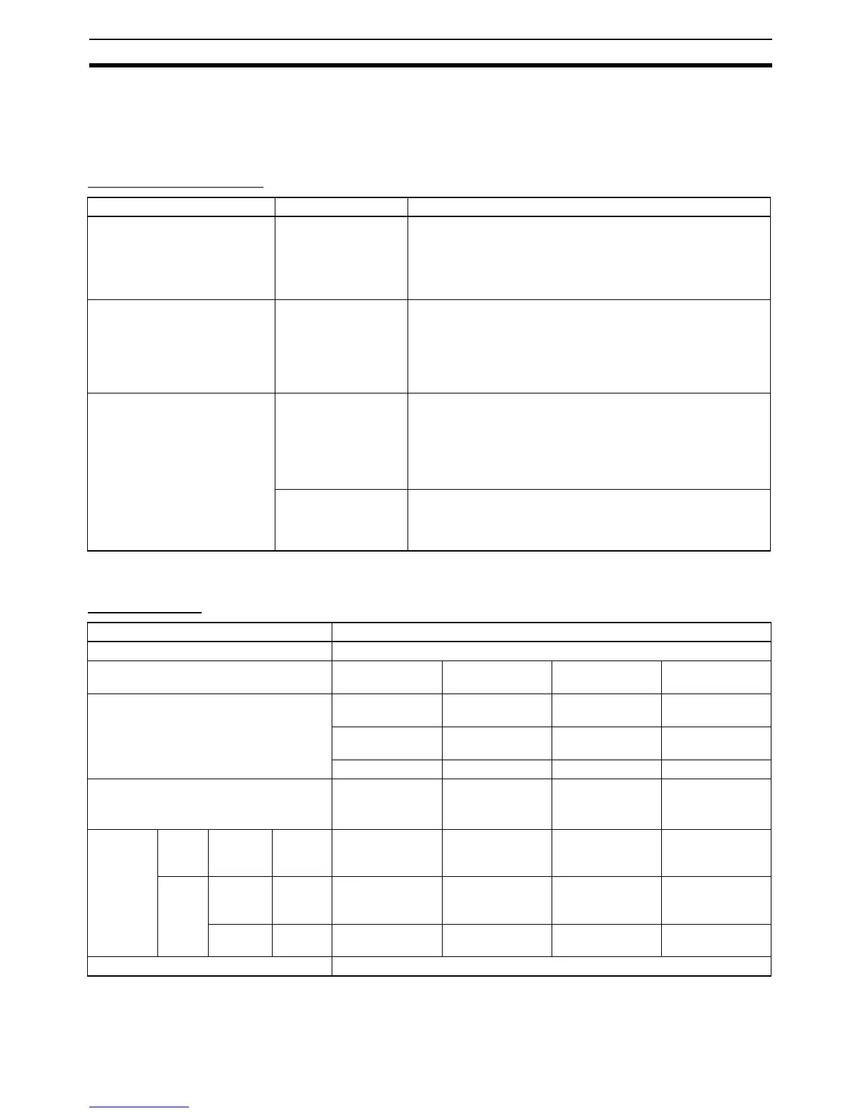
Purpose Function used Description
Receive incremental rotary
encoder inputs to calculate
length or position.
High-speed counter
function
Built-in input terminals can be used for high-speed counter
inputs.
The PV for the high-speed counters are stored in the Auxiliary
Area.
The counters can be operated in ring mode or linear mode.
Measure a workpiece's length
or position.
(Start counting when a certain
condition is established or
pause counting when a certain
condition is established.)
High-speed Counter
Gate Bit
The high-speed counter can be started or stopped (PV held)
from the Unit's program by turning ON/OFF the High-speed
Counter Gate Bit when the desired condition is met.
Measure a workpiece's speed
from its position data (frequency
measurement.)
PRV(881) HIGH-
SPEED COUNTER
PV READ
The PRV(881) instruction can be used to measure the pulse fre-
quency.
• Range with differential phase inputs: 0 to 50 kHz (Y models: 0
to 500 kHz)
• Range with all other input modes: 0 to 100 kHz (Y models: 0 to
1 MHz)
PRV2(883) PULSE
FREQUENCY CON-
VERT
PRV2(883) reads the pulse frequency and converts it to a rota-
tional speed (r/min) or it converts the counter PV to a total num-
ber of rotations. Results are calculated by the number of pulses/
rotation.
Item Specification
Number of high-speed counters 4 (High-speed counters 0 to 3)
Pulse input modes (Selected in the PLC
Setup)
Differential phase
inputs
Up/down inputs Pulse + direction
inputs
Increment inputs
Input terminal allocation Phase-A input Increment pulse
input
Pulse input Increment pulse
input
Phase-B input Decrement pulse
input
Direction input ---
Phase-Z input Reset input Reset input Reset input
Input method Differential phase,
4x
(Fixed)
Two single-phase
inputs
Single-phase
pulse + direction
inputs
Single-phase
input
Response
frequency
X/XA
CPU
Unit
Counters
0 to 3
24 VDC
inputs
50 kHz 100 kHz 100 kHz 100 kHz
Y CPU
Unit
Counters
0 and 1
Line
driver
inputs
500 kHz 1 MHz 1 MHz 1 MHz
Counters
2 and 3
24 VDC
inputs
50 kHz 100 kHz 100 kHz 100 kHz
Counting mode Linear mode or circular (ring) mode (Select in the PLC Setup.)

 Loading...


