6.11.3.3 Assigning the machining plane
You can select the machining plane in which the contour created with the DXF reader should
be located.
Procedure
1. The DXF file is opened in the editor.
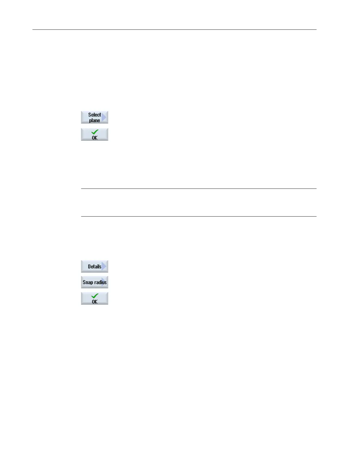
2. Press the "Select plane" softkey.
The "Select Plane" window opens.
3. Select the desired plane and press the "OK" softkey.
6.11.3.4 Setting the tolerance
To allow even inaccurately created drawings to be used, i.e. to compensate for gaps in the
geometry, you can enter a snap radius in millimeters. This relates elements.
Note
Large snap radius
The larger that the snap radius is set, the larger the number of available following elements.
Procedure
1. The DXF file is opened in the editor.
2. Press the "Details" and "Snap radius" softkeys.
The "Input" window appears.
3. Enter the desired value and press the "OK" softkey.
6.11.3.5 Selecting the machining range / deleting the range and element
You can select ranges in the DXF file and therefore reduce the elements. After accepting the
2nd position, only the contents of the selected rectangle are displayed. Contours are cut to the
rectangle.
Requirement
The DXF file is open in the editor.
Machining the workpiece
6.11 Working with DXF files
Milling
Operating Manual, 08/2018, 6FC5398-7CP41-0BA0 231

 Loading...


