8.4 Fundamentals
8.4.1 Machining planes
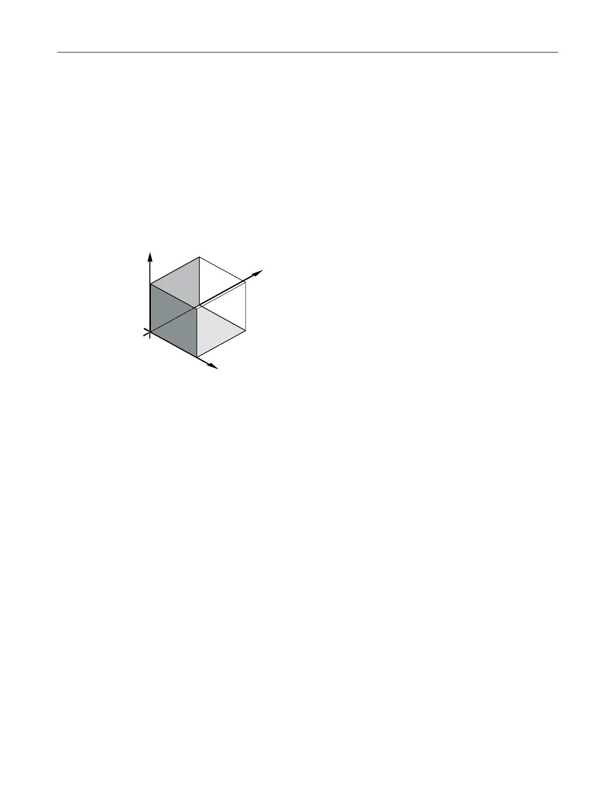
A plane is defined by means of two coordinate axes. The third coordinate axis (tool axis) is
perpendicular to this plane and determines the infeed direction of the tool (e.g. for 2½-D
machining).
When programming, it is necessary to specify the working plane so that the control system
can calculate the tool offset values correctly. The plane is also relevant to certain types of
circular programming and polar coordinates.
Working planes
Working planes are defined as follows:
Plane Tool axis
X/Y G17 Z
Z/X G18 Y
Y/Z G19 X
8.4.2 Current planes in cycles and input screens
Each input screen has a selection box for the planes, if the planes have not been specified by
NC machine data.
● Empty (for compatibility reasons to screen forms without plane)
● G17 (XY)
● G18 (ZX)
● G19 (YZ)
There are parameters in the cycle screens whose names depend on this plane setting. These
are usually parameters that refer to positions of the axes, such as reference point of a position
pattern in the plane or depth specification when drilling in the tool axis.
Generating a G code program
8.4 Fundamentals
Milling
Operating Manual, 08/2018, 6FC5398-7CP41-0BA0 301

 Loading...


