Function introduction
AFG31000 Series Arbitrary Function Generator User's Manual 77
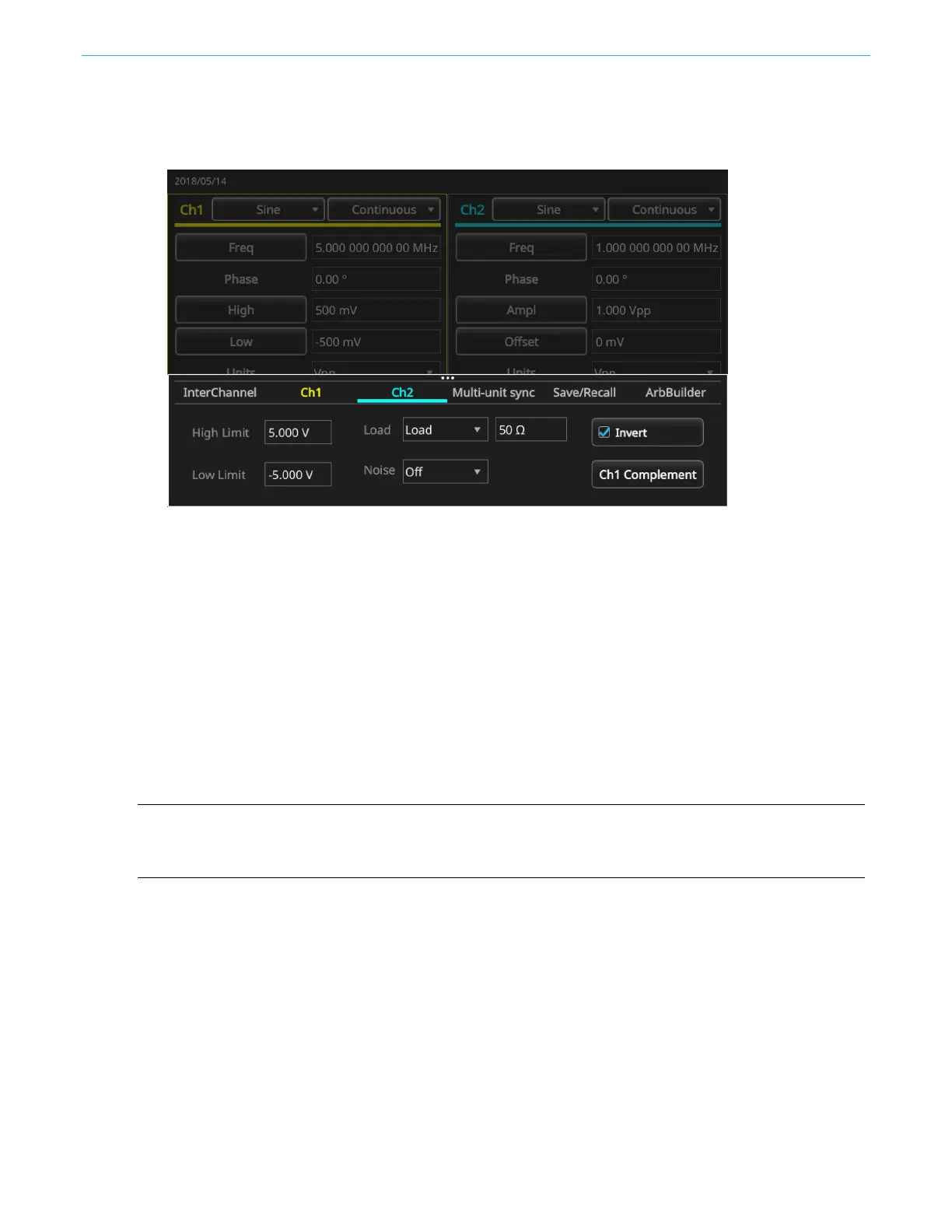
4. Select the CH2 tab and select the CH1 Complement button. The CH2 wave shape and timing
settings are copied from CH1, and the CH2 amplitude settings are inverted from CH1.
Figure 53: Ch2 tab and CH1 Complement button
External reference clock
The external reference input (EXT REF INPUT) and the external reference output (EXT REF
OUTPUT) connectors are on the AFG31000 Series Arbitrary Function Generator rear panel. The
instrument can use the internal or external signal as a reference signal.
The external reference input and output connectors are used for synchronizing multiple AFG31000
Series instruments. The instrument can use the internal source or an external source as a reference
signal. When the internal reference is activated, a 10 MHz reference signal is output on the rear panel
EXT REF OUT connector. This output signal synchronizes other devices to the instrument.
When the external reference input is activated, the rear panel EXT REF INPUT connector is used as
the input for an external reference signal. The instrument is synchronized using this external
reference signal.
NOTE. The external reference clock must be set to 10 MHz. When external is selected, make sure that
you have connected the appropriate cable for the 10 MHz signal. Also, when internal is selected, the
internal 10 MHz clock takes effect immediately.
To select a reference signal:
1. Select Utility.
2. Select System.
3. In the Clock Ref settings, toggle between Internal and External. If you are using the EXT REF
INPUT, make sure your connections are correct.
 Loading...


