Function introduction
90 AFG31000 Series Arbitrary Function Generator User's Manual
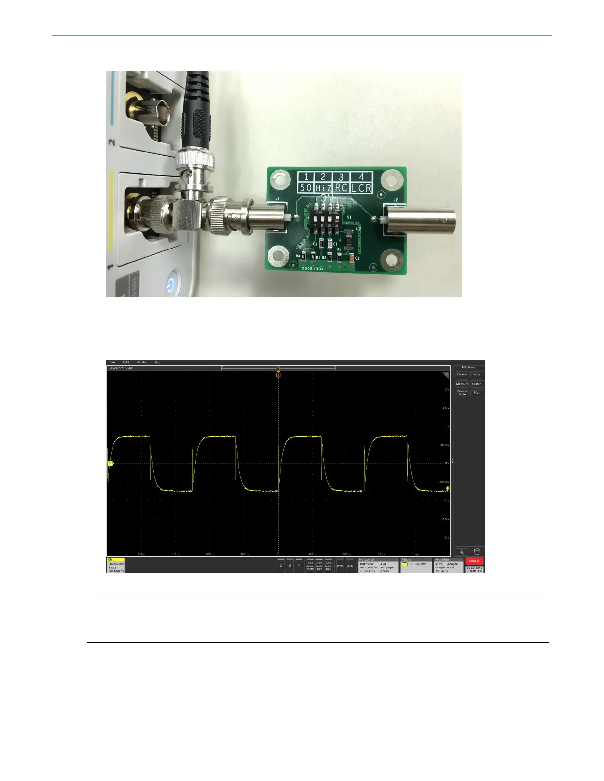
Figure 65: BNC connectivity to AFG31000
7. Make sure the switch on the demo board is set to LCR (complex impedance including resistive,
capacitive, and inductive load)
8. Adjust the oscilloscope to observe the waveform.
Figure 66: Complex load
NOTE. You can see how the input impedance of the DUT impacts the waveform in terms of amplitude
(pure resistive load) and shape (capacitive-inductive load), but the waveform shape shown on the
instrument is still a perfect square.
Setup InstaView on the AFG31000
1. Press the InstaView
TM
button on the front panel to open the settings window.
 Loading...


