Home
Volkswagen
Automobile
Passat 1996
Volkswagen Passat 1996 User Manual
5
of 1
of 1 rating
369 pages
Give review
Manual
Specs
To Next Page
To Next Page
To Previous Page
To Previous Page
Loading...
4
0
-7
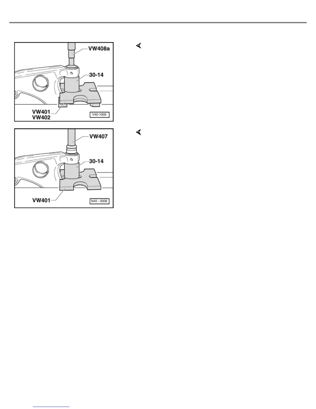
Fig. 1
Front co
n
trol arm mounting, pressi
n
g
out
Note:
Before pressing in, coat with acid-free lubricant, e.g.
soft soap.
Fig. 2
Front co
n
trol arm mounting, pressi
n
g in
Page
7
of
82
Front Wheel Suspension, Shafts and Axle
12/7/2004
http://ebahn.bentleypublishers.com/vw/servlet/Display?action=Goto&ty
p
e=repair&id=VW.B4.SU01.40.1
20
22
Table of Contents
Default Chapter
3
Front Suspension
3
Rear Suspension
3
General, Technical Data
3
Anti-Lock Brake System
4
Brakes - Mechanical Components
4
Wheels, Tires, Wheel Alignment
4
Brakes - Hydraulic Components
5
Steering
6
Suspension, Wheels, Brakes, Steering
7
Technical Data
7
Brakes
9
Wheels, Tires
12
Front Suspension, Servicing (Base Suspension)
15
Sub-Frame, Stabilizer Bar and Control Arm (Base Suspension)
16
Hex Bolt, 35 Nm (26 Ft Lb) and Ball Joint
17
Air Deflector Plate
17
Control Arm
17
Captive Lock Nuts
17
Table of Contents
18
Connecting Link
18
Control Arm Front Mounting
18
Control Arm Rear Mounting
18
Hex Bolt M 12 X 1.5 X 82/65/78
18
Connecting Link Mounting
19
Self-Locking Hex Nut, 25 Nm (18 Ft Lb)
19
Sub-Frame
19
Washer
19
Vibration Damper/Cap Nut
20
Stabilizer Bar Mounting/Clamp
20
Self-Locking Hex Nut, 25Nm (18 Ft Lb)
20
Hex Bolt, 65 Nm (48 Ft Lb)/25 Nm (18 Ft Lb)
20
Front Control Arm Mounting, Pressing in
21
Front Control Arm Mounting, Pressingout
21
Control Arm Rear Mounting, Installation Position
22
Control Arm Rear Mounting, Pressing out and in
22
Supporting Engine/Transmission Assembly with 10-222 a and Legs 10-222 A/1
23
Ball Joint, Checking (Base and Plus Suspension)
24
Checking Axial Clearance
24
Checking Radial Play
24
Reworking Cap Nut in Side Member (Base and Plus Suspension)
25
When Drilling out Proceed as Follows
25
Bolt/Washer Assemblies for Sub-Frame
26
Wheel Bearing, Suspension Strut and Drive Shaft, Removing and Installing (Base Running Gear)
28
Self-Locking Nut, 265 Nm (195 Ft Lb)
29
Hub
29
Brake Disc/Caliper
29
Hex Bolt, 10 Nm (7 Ft Lb)
30
Speed Sensor Rotor
30
Splash Plate
30
Wheel Bearing Housing
30
Drive Shaft and Circlip
31
Self-Locking Bolt/Washer Assembly, 125 Nm (92 Ft Lb)
31
Self-Locking Hex Nut, 95Nm (70 Ft Lb)
31
Socket Head Multi-Point Bolt, 45 Nm (33 Ft Lb)
31
Bracket
32
Self-Locking Hex Nut, 60 Nm (44 Ft Lb)
32
Suspension Strut Bearing
32
Tie Rod
32
Fig. 2
32
Suspension Strut to Body, Loosening and Tightening
33
Wheel Bearing Housing/Suspension Strut Joint, Separating
33
Fig. 1
33
Ball Joint/Control Arm Connection, Separating
34
Hub, Pressing out of Wheel Bearing Housing
34
Bearing Race, Pulling out of Hub
35
Wheel Bearing, Pressing out of Wheel Bearing Housing
35
Wheel Bearing, Pressing into Wheel Bearing Housing
36
Hub, Pressing into Wheel Bearing Housing
36
Front Suspension Strut, Servicing (Base and Plus Suspension)
37
Shock Absorber
37
Buffer Stop
37
Protective Sleeve
37
Coil Spring/Spring Plate
38
Axial Bearing
38
Hex Nut, 60 Nm (44 Ft Lb)
38
Suspension Strut Mounting
38
Hex Nut, Loosening and Tightening
39
Spring, Removing and Installing
39
Front Suspension, Servicing (Plus Suspension)
40
Sub-Frame, Stabilizer Bar and Control Arm, Removing and Installing (Plus Suspension)
41
Hex Bolt, 35 Nm (26 Ft Lb)
41
Ball Joint/Captive Locknuts
41
Self-Locking Hex Nut, 45 Nm (33 Ft Lb)
41
Control Arm Rear/Front Mounting
42
Air Guide Plate
42
Hex Bolt M 12 X 1.5 X 78/65
42
Nm (52 Ft Lb) and Turn 90 Further
42
Pressing out Fig
42
Connecting Link
42
With Rubber Mounting
42
Mounting Forconnecting Link
43
Hex Bolt M 12 X 1.5 X 82
43
Hex Bolt, 65 Nm (48 Ft Lb)
43
Clamp for Stabilizer Bar
43
Nm (37 Ft Lb) and Turn 90 Further
43
Stabilizer Bar Mounting
44
Cap Nut
44
Control Arm Front Mounting, Pressing out and in
45
Engine/Transmission Assembly, Supporting with 10-222 a and 10-222 A/3
46
Ball Joint, Removing and Installing (Plus Running Gear)
47
Removing
47
Installing
48
Tightening Torques
49
Wheel Bearing and Suspension Strut, Removing and Installing (Plus Suspension)
50
Wheel Bolt, 110 Nm (81 Ft Lb) and Self-Locking 12-Point Nut
50
Screw
50
Brake Disc
50
Brake Caliper
51
Countersunk Screw
51
Wheel Bearing
52
Self-Locking Hex Nut, 35 Nm (26 Ft Lb)
52
Self-Locking Bolt/Washer, 125 Nm (92 Ft Lb)
52
Drive Shaft
52
Hex Bolt
53
Stop
53
Self-Locking Hex Nut, 60 and 95 Nm (44 and 70 Ft Lb)
53
Suspension Strut
53
Inner Race, Pulling off Hub
55
Drive Shaft, Removing and Installing (Plus Running Gear)
57
Drive Shaft, Repairing
60
Drive Shaft, Removing and Installing
60
Circlip
61
Gasket
61
Inner Constant Velocity Joint 100 MM Diameter
61
Dished Washer
61
Boot for 100 MM Diameter Constant Velocity Joint
62
Clamp
62
Boot for 90 MM Diameter Constant Velocity Joint
63
Dished/Thrust Washer
64
Outer Constant Velocity Joint, 90 MM Diameter
64
Vibration Damper
65
Protective Cap
66
Hex Bolt, 35 Nm (26 Ftlb)
66
Boot for 90 MM
66
Diameter Constant
66
Velocity Joint
66
Polyester Elastomer Version
66
Check for Tears and Chafing
66
Briefly Ventilate Boot
66
Before Tensioning the Small Clamp Fig
66
Vibration Damper, Removing and Installing
67
Vibration Damper, Installation Position
67
Installation Position for
67
Fig. 1
67
Outer Constant Velocity Joint, Removing
68
Inner Constant Velocity Joint, Pressing off
68
Inner Constant Velocity Joint, Pressing on
69
Installation Position of Left Drive Shaft Transmission End Joint Boot - Rubber Version
69
Installation Position of Right Drive Shaft Transmission End Joint Boot
70
Joint Boot, Ventilating
70
Larger Clamp, Tensioning
71
Smaller Clamp, Tensioning 40
71
Installation Position of Left Drive Shaft Wheel End Joint Boot, Shaft Diameter 27 MM
72
Installation Position of Left Drive Shaft, Wheel End, Shaft Diameter 22 MM
72
Installation Position of Right Drive Shaft, Wheel End Joint Boot
73
Outer Constant Velocity Joint, Checking
74
Inner Constant Velocity Joint, Checking
76
Checking Operation of Constant Velocity Joint
78
Drive Shaft with Tripod Joint, Repairing
79
Outer Constant Velocity Joint
79
Thrust Ring
79
Boot for Constant Velocity Joint, 90 MM Dia
80
Drive Shaft, Left, with Inner Tripod Joint
80
Clamp
80
Always Replace
80
And Fig
80
Inner Splined Screw, 45 Nm (33 Ft Lb)
81
Drive Shaft, Right, with Inner Tripod Joint
81
Constant Velocity Joint, Outer, Removing
82
Boot, Ventilating
82
Clamp, Tightening on Large Diameter
83
Clamp, Tightening on Small Diameter
83
Drive Axle with Triple-Rotor Joint, Removing and Installing
84
Removing Right-Side Drive Axle
84
Removing Left-Side Drive Axle
84
Drive Axle with Triple-Rotorjoint, Servicing
87
Outer Constant Velocity (CV) Joint
87
Belleville Spring
87
Boot
87
Cover
88
Rectangular Sealing Ring
88
O-Ring
88
Triple-Rotor Star
88
Removing Outer CV Joint
89
Tightening Outer CV Joint Boot Clamp
90
Tightening Small End Clamp
90
Triple-Rotor Joint, Disassembling
91
Triple-Rotor Joint, Assembling
94
Rear Wheel Suspension, Shafts and Axle
97
Rear Axle, Servicing (Vehicles with Front Wheel Drive)
97
Wheel Bolt 110 Nm (81 Ft Lb)
97
Self-Locking Hex Nut, 70Nm (52 Ft Lb)
97
80 Nm (59 Ft Lb)
98
Shouldered Bolt, 70 Nm (52 Ft Lb)
98
Mounting Bracket with Retainer for Brake Pressure Regulator
99
Regulator Spring Bracket
99
Bonded Rubber Mounting
99
Axle Beam
99
Suspension Strut at Body, Removing and Installing
100
Suspension Strut, Removing and Installing
101
Bolting Mounting Bracket to Axle Beam
101
Bonded Rubber Mounting, Pressing 1St/2St Half out of Axle Beam
102
Rubber Bonded Mounting, Installation Position
103
Rubber Bonded Mounting, Presssing into Axle Beam
103
Reworking Cap Nut in Side Member (Front Wheel Drive Vehicles)
104
Suspension Strut, Disassembling and Assembling (Front Wheel Drive Vehicles)
105
Upper Rubber Mounting
105
Gasket (Foam)
105
Spacer Tube
106
Lower Rubber Mounting
106
Metal Cap
106
Spring Seat
106
Stop Buffer
107
Protective Tube
107
Plastic Cap
107
Coil Spring
107
Spring Seat, Installation Position
109
Suspension Strut Mounting to Shock Absorber Bushing, Aligning
110
Cap in Suspension Strut Mounting, Pressing in
110
Drum Brakes (Front Wheel Drive Vehicles), Wheel Bearings, Servicing
111
Grease Cap
111
Cotter Pin
112
Hex Nut
112
Locking Ring
112
Stub Axle
112
Brake Backing Plate
113
Oil Seal
113
Hex Bolt, 60 Nm (44 Ft Lb)
113
Inner Wheel Bearing
113
Brake Drum
114
Grease Cap, Pressing off
115
Grease Cap, Driving on
116
Wheel Bearing Play, Adjusting
116
Brake Shoe Adjustment, Releasing
117
Outer Wheel Bearing Outer Race, Pressing in
117
Inner Wheel Bearing Outer Race, Pressing in
118
Oil Seal, Driving in
118
Rotor, Pressing in
119
Wheel Bearings, Servicing - Disc Brakes (Front Wheel Drive Vehicles)
120
Hex Socket Head Bolt, 10 Nm (7 Ft Lb)
120
Speed Sensor
121
Brake Hose Bracket
121
Guide Pins
121
Pad Retaining Spring
121
Cover Ring
122
Pad Carrier
122
Brake Pads
122
Outer Wheel Bearing
122
Thrust Washer
123
Wheel Bolt, 110 Nm (81 Ft Lb)
123
Backing Plate
124
Parking Brake Cable
124
Spring Clip
124
Cover Ring, Installation Position
127
Rear Axle, Servicing (Four Heel Drive Vehicles)
129
Final Drive Mounting Bracket and Carrier
130
Propshaft
131
Anti-Roll Bar
131
Rear Axle Mounting Bracket
131
Hex Bolt, 85 Nm (63 Ft Lb)
132
Hex Bolt for Seat Belt Strut, 25 Nm (18 Ft Lb)
132
Suspension Strut from Control Arm, Removing and Installing
133
Driveshaft and Drive Axle, Removing and Installing at Differential
133
Stabilizer Bar, Removing and Installing
134
Control Arm, Removing and Installing
135
Rubber Bonded Mounting, Removing
135
Bonded Rubber Mounting, Installing
136
Rubber Mounting to Correct Camber/Toe
137
Final Drive, Removing and Installing from Axle Beam
138
Installation Position, Determining
139
Rubber Bonded Mounting, Installing
139
Mounting Bracket and Final Drive Carrier, Removing and Installing
140
Remove and Install Complete
140
Final Drive Bonded Rubber Bushing, Pressing in and out
140
Mounting Bracket on Body, Removing and Installing
141
Rear Drive Shafts, Servicing
142
Inner Constant Velocity Joint, 81 MM Diameter
143
Boot for 94 MM Diameter Constant Velocity Joint
144
Hose Clamp
144
Boot for 81 MM Diameter Constant Velocity Joint
145
Outer Constant Velocity Joint: 81 MM Diameter
146
Inner Support Rings
146
Reworking Cap Nut in Side Member (Four Wheel Drive Vehicles)
147
Suspension Strut, Disassembling and Assembling (Four Wheel Drive Vehicles)
149
Seal
149
Self Locking Hex Nut, 30 Nm (22 Ft Lb)
149
Stop Buffer Mounting
150
Ring (Aluminium)
150
Packing
151
Lower Spring Plate
151
Lower Spring Plate, Installation Position
152
Suspension Strut Mounting to Spring Seat, Installation Position
153
Cap, Pressing into Suspension Strut Mounting
154
Wheel Bearings, Servicing - Disc Brakes (Four-Wheel Drive Vehicles)
155
Self Locking Hex Socket Head Bolt, 60 Nm (44 Ft Lb)
155
Self Locking Hex Bolt, 35 Nm (26 Ft Lb)
155
Pad Securing Springs
156
Self-Locking Hex Nut
157
Shim
157
Drive Shaft with Speed Sensor Rotor
159
Brake Line
159
Hub, Pressing out
160
Wheel Bearing, Pressing out
160
Inner Race, Pulling off of Hub
161
Wheel Bearing, Pressing in
161
Hub, Pressing in
162
Speed Sensor Rotor, Pressing in
162
Vehicle Alignment
163
Test Requirements
163
Vehicle Alignment Specifications (Front Wheel Drive Vehicles)
164
Vehicle Alignment Specifications (Four Wheel Drive Vehicles)
166
Front Wheel Camber, Adjusting
168
Calculating the Direction of Travel
169
Anti-Locking Brake System (ABS) and Anti-Locking Brake System with Electronic Differential Lock (ABS/EDL) Teves 04
170
Notes for Repair Work on ABS, ABS/EDL
171
Control Module, Removing and Installing
173
Location
173
Wheel Speed Sensor and Rotor for Speed Sensor, Removing and Installing
174
Rotors
174
Rear Axle
174
Anti-Lock Brake System (ABS) and ABS with Electronic Differential Lock (ABS/EDL), Teves 20 GI
175
Safety Precautions
176
ABS, ABS/EDL Hydraulic Unit, Vacuum Brake Booster and Brake Master Cylinder (Teves 20 GI), Servicing
178
Brake Servo (Vacuum Brake Booster)
178
Brake Master Cylinder
178
Brake Fluid Reservoir
178
Rubber Damper
179
Retainer
179
ABS Hydraulic Unit/Control Module
179
Brake Line Connection
179
ABS Hydraulic Unit and ABS Control Module (Teves 20 GI), Removing and Installing
180
Sealing Plug Kit Part No. 1H0 698 311 A:
180
Brake Hydraulic System, Bleeding and Filling
186
Vehicles with ABS/EDL
186
Assembly Overview - Hydraulic Unit, Brake Servo/Brake Master Cylinder
187
Brake Pedal Position Sensor
187
Sealing Ring
188
Brake Servo
188
Carrier Plate
188
Pin
188
Hex Socket Head Screw for Brake Fluid Reservoir
189
Series Resistor
189
Tandem Brake Master Cylinder
189
Protective Plate
189
ABS Hydraulic Unit
190
ABS/EDL Hydraulic Unit
190
Torx Bolts (T 25)
190
Hydraulic Unit, Removing and Installing
192
Brake Pedal Position Sensor, Removing and Installing
194
Front Brakes, Servicing (Girling Caliper)
197
Brake Disc, Not Ventilated
198
Brake Disc, Ventilated
198
Brake Pad
199
Wheel Speed Sensor Rotor
199
Brake Carrier with Guide Pins and Protective Caps
200
Heat Shield
200
Brake Caliper Housing
200
Self-Locking Hex Bolt, 35 Nm (26 Ft Lb)
201
Guide Pin
201
Ribbed Bolt, 125 Nm (92 Ft Lb)
201
Brake Pads, Removing and Installing
202
Retaining Spring
205
Brake Carrier
205
Guide Pins, 25 Nm (18 Ft Lb)
206
Banjo Bolt, 30 Nm (22 Ft Lb)
206
Countersunk Bolt
207
Rear Wheel Brakes, Servicing (Drum Brakes)
211
Wheel Speed Sensor
213
Backing Plate with Brake Shoes
213
Rear Wheel Brakes, Servicing
215
After Working on the Rear Wheel Brakes
215
Spring Plate
215
Brake Shoe with Lever for Parking Brake
215
Upper Return Spring
216
Lower Return Spring
216
Wedge Spring
216
Brake Shoe
216
Wheel Cylinder
217
Wedge
217
Push Rod
217
Locating Spring
217
Wheel Cylinder, Checking for Leaks
218
Brake Shoes, Removing and Installing
219
Parking Brake, Adjusting (Drum Brakes)
222
Rear Wheel Brakes, Servicing (Disc Brakes)
223
Girling Rear Wheel Disc Brakes (Front and Four Wheel Drive Vehicles)
223
Hex Socket Head Bolt
223
Nm (7 Ft Lb)
223
Wheel Speed Sensor
223
Abs
223
Insert with Lubricating Paste
223
Hex Socket Head Bolt, 65 Nm (48 Ft Lb)
224
Self-Locking Bolt, 35 Nm (26 Ft Lb)
224
Pad Retaining Springs
224
Backing Plate Ring
224
Brake Carrier with Guide Pins and Protective Cap
225
Dished Spring Washer
228
Hex Bolt, 60 Nm (44 Ft Lb)
228
Parking Brake, Adjusting (Disc Brakes)
232
Parking Brake Lever Assembly Overview
233
Hand Grip
233
Adjusting Nut
233
Lock Nut
234
Compensator
234
Parking Brake Lever Trim
234
Parking Brake Cable Installation Position
235
Hand Grip, Removing
235
Center Console, Removing
236
Brake Pedal/Brake Servo, Removing and Installing
237
Brake Pedal Return Spring
238
Return Spring Mounting Tube
238
Brake Pedal Mounting Bushing
238
Brake/Clutch Pedal
238
Securing Clip
239
Brake Light Switch
239
Brake Pedal, Removing and Installing
240
Brake Light Switch, Adjusting
241
Assembly Overview: Brake Master Cylinder/Brake Servo
242
Self-Locking Hex Nut, 20 Nm (15 Ft Lb)
242
Mounting Bracket
242
Sealing Plug
244
Non-Return Valve
245
Girling Front Brake Caliper, Servicing
246
Protective Seal
246
Bleed Valve
246
Piston
247
Front Brake Caliper Pistons, Removing and Installing
248
Front Brake Caliper, Servicing (Teves/Ate)
251
Guide Pin, 25 Nm (18 Ft Lb)
251
Mounting Bushing
251
Piston Seal
252
Piston, Pressing out of Cylinder Using Compressed Air
253
Piston Seal, Removing
253
Protective Seal, Installing
254
Piston, Installing
255
Rear Brake Caliper, Servicing
256
Self-Locking Bolts, 35 Nm (26 Ft Lb)
256
Dust Cap
257
Bleeder Valve
257
Brake Caliper Housing with Parking Brake Cable Lever
258
Brake Carrier with Guide Pin and Protective Cap
259
Rear Brake Caliper Piston, Removing and Installing
260
Pre-Bleeding Brake Caliper
263
Brake Pressure Regulator, Checking and Adjusting
264
Vehicles Without ABS, Vehicles with ABS, ABS/EDS, Teves 04
264
Checking Operation
264
Checking and Adjusting Pressure
264
Load Dependent Brake Pressure Regulator Specifications
266
Adjusting Regulator
267
Brake System, Bleeding (Vehicles with and Without ABS, ABS/EDL)
268
Changing Brake Fluid
268
Brake System, Bleeding (with Pressure Bleeder VAS 5234)
269
Bleeding Sequence
269
Brake System, Bleeding (Without Pressure Bleeder)
270
Assembly Overview: Steering Column, Column Tube, Steering Wheel and Airbag Steering Wheel
271
Cover Plate
272
Hex Nut, 50 Nm (37 Ft Lb)
272
Airbag Unit
272
Steering Wheel for Airbag
272
Steering Column Switch/Steering Lock Housing
273
Upper Trim
273
Support Ring
273
Steering Column
273
Lower Steering Column Bearing
274
Shear Bolt
274
Column Tube
274
Lower Trim
274
Splined Adapter Sleeve, Removing
275
Splined Adapter Sleeve, Installing
275
Length of Steering Column, Checking
276
Steering Column, Pre-Assembling
276
Airbag Unit, Removing and Installing
277
Airbag Steering Wheel, Removing and Installing
278
Airbag Spiral Spring, Removing and Installing
280
Column Tube for Height Adjustable Steering Wheel, Removing and Installing
281
Operating Lever
281
Packing Plate
281
Rubber Stop
281
Clamping Sleeve
282
Bolt with Left-Hand Thread
282
Locking Plate Nut, 8 Nm (70 In. Ib)
282
Pump Delivery Pressure, Checking
283
Power Steering Gear, Removing and Installing
285
Assembly Overview: Power Assisted Steering Box (TRW)
289
Self-Locking Nut 35 Nm (26 Ft Lb)
290
Self-Locking 30 Nm (22 Ft Lb)
290
Rubber Mounting
290
Right-Hand Tie Rod
290
Left-Hand Tie Rod
291
Hex Nut 50 Nm (37 Ft Lb)
291
Steering Gear
292
Tie Rod End
292
Hex Nut 30 Nm (22 Ft Lb)
292
Universal Joint
292
Threaded Connection 30 Nm (22 Ft Lb)
293
Power Steering Gear, Adjusting (TRW)
294
Adjusting Steering Box
294
Power Steering Gear, Disassembling and Reassembling (TRW)
295
Lock Washer
296
Toothed Rod Guide
296
Pressure Compensating Tube
297
Toothed Rod
297
Plug
297
Adjusting Screw with Lock Nut, 60 Nm (44 Ft Lb)
298
Pressure Spring/Piece
298
Housing
298
Inverted Tube Nut, 30 Nm (22 Ft Lb)
298
Valve Body
299
Adhesive Film
299
Roller Bearing
300
Ball Bearing
300
Self-Locking Hex Nut, 30 Nm (22 Ft Lb)
300
Locking Screw, 40 Nm (30 Ft Lb)
300
Pipe
301
Power Steering Gear, Disassembling
302
Inner Sealing Ring for Toothed Rod, Pulling out
308
Parts, Cleaning and Checking
309
Checking Toothed Rod for Scoring
310
Sealing Ring on Toothed Rod, Replacing
311
Sealing Rings, Installing on Toothed Rod Piston
312
Power Steering Gear, Assembling
313
Inner Sealing Ring for Toothed Rod, Installing
314
Toothed Rod, Installing in Housing
315
Valve Body, Installing
317
Adhesive Tape, Applying
320
Power Steering Gear, Adjusting with New Toothed Rod
321
Assembly Overview: Power Steering Gear (ZF)
324
Power Steering Gear
325
Hose Clip
325
Lock Nut, 50 Nm (37 Ft Lb)
328
Tie Rod Ball Joint
328
Pressure Balance Pipe
328
Data Plate and Company Initials
328
Power Steering Gear, Adjusting (ZF)
329
Power Steering Gear, Disassembling and Reassembling (ZF)
330
Center Roller Bearing for Valve Body, Removing
335
Sealing Ring for Valve Body, Removing
336
Inner Sealing Ring for Toothed Rod, Removing
337
Inner Sealing Rod for Toothed Rod, Installing
341
Toothed Rod, Installing in the Housing
343
Tie Rods, Removing and Installing (Power Steering Gear - TRW and ZF)
347
Boot, Installing
351
Tension Hose Clamps with Pliers VAG 1275 or Equivalent
352
Left-Hand Tie Rod Length, Checking and Adjusting
354
Assembly Overview: Vane Pump, Reservoir and Hydraulic Lines (Vehicles with 4-Cyl. Engines)
355
Cooling Line
356
Suction Line
356
Hydraulic Pump
356
Pressure Line Union
357
Banjo Bolt, 35 Nm (26 Ft Lb)
357
Assembly Overview: Hydraulic Lines, Reservoir (Vehicles with 4-Cyl. Engines)
358
Return Line, 30 Nm (22 Ft Lb)
358
Pressure Line, 30 Nm (22 Ft Lb)
358
Rubber Ring
358
Self-Tapping Screw
359
Hose/Return/Suction Clamp
359
Threaded Stud
359
Power Steering Vane Pump, Removing and Installing (Vehicles with 4-Cyl. Engines)
360
Suction Hose
360
Tensioning Bolt
360
20 Nm (15 Ft Ib)
361
Front Swivel Bracket
361
Adjustment Bracket
361
V-Belts
361
V-Belt Pulley
362
20 Nm (15 Ft Lb)
362
Rear Swivel Bracket
362
Vane Pump
362
V-Belts, Tensioning (4-Cyl. Engines)
363
Specification
363
Assembly Overview: Pressure and Coolingl Ines (Vehicles with VR6 Engine)
364
Reservoir
364
Hose Clamp, 3 Nm (27 In. Lb)
364
Return Line
365
Pressure Hose, Securing (Vehicles with Manual Transmission)
366
Pressure Hose, Securing (Vehicles with Automatic Transmission)
366
Power Steering Vane Pump, Removing and Installing (Vehicles with VR6 Engine)
367
Ribbed Belts
368
Hex Socket Head Bolt, 25 Nm (18 Ft Lb)
369
Hex Bolt, M8 X 30, 25 Nm (18 Ft Lb)
369
Hex Socket Head Bolt, M8 X 20, 25 Nm (18 Ft Lb)
369
Hex Socket Head Bolt, M8 X 30, 25 Nm (18 Ft Lb)
369
Other manuals for Volkswagen Passat 1996
Official Factory Repair Manual
307 pages
5
Based on 1 rating
Ask a question
Give review
Questions and Answers:
Need help?
Do you have a question about the Volkswagen Passat 1996 and is the answer not in the manual?
Ask a question
Volkswagen Passat 1996 Specifications
General
Brand
Volkswagen
Model
Passat 1996
Category
Automobile
Language
English
Related product manuals
Volkswagen Passat 1997
103 pages
Volkswagen Passat 1995
307 pages
Volkswagen Passat
369 pages
Volkswagen Passat B5
122 pages
Volkswagen Passat W8
52 pages
Volkswagen 2014 Passat
19 pages
Volkswagen Passat 2012
180 pages
Volkswagen Passat 2006
299 pages
Volkswagen Passat 2022
9 pages
Volkswagen Passat 2021
9 pages
Volkswagen Passat 2011
475 pages
Volkswagen Passat Estate 2020
23 pages
 Loading...