40-53
The damper consists of two halves. Both halves are
joined to one another by spring pins (arrow).
Installation position Fig. 1
Note:
Fig. 1 Vibration damper, removing and
installing
Only replace vibration damper with drive shaft
removed
Before driving in spring pin protect shaft paint
finish against damage.
To prevent axial movement apply adhesive tape
or a suitable adhesive to internal diameter.
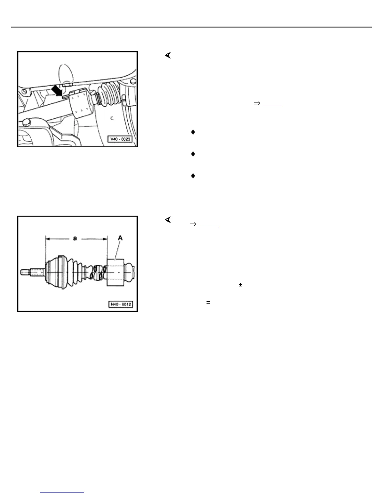
When installing vibration damper -A- note correct
installation position. Ensure dimension "a" is
maintained.
Dim. "a" = 521 1 mm right shaft
264 1 mm left shaft (if installed)
Fig. 1
1
Vibration damper, installation position
Front Wheel Suspension, Shafts and Axle
http://ebahn.bentleypublishers.com/vw/servlet/Display?action=Goto&type=repair&id=VW.B4.SU01.40.1
 Loading...