ENGINE
3-16
EAS21080
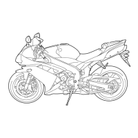
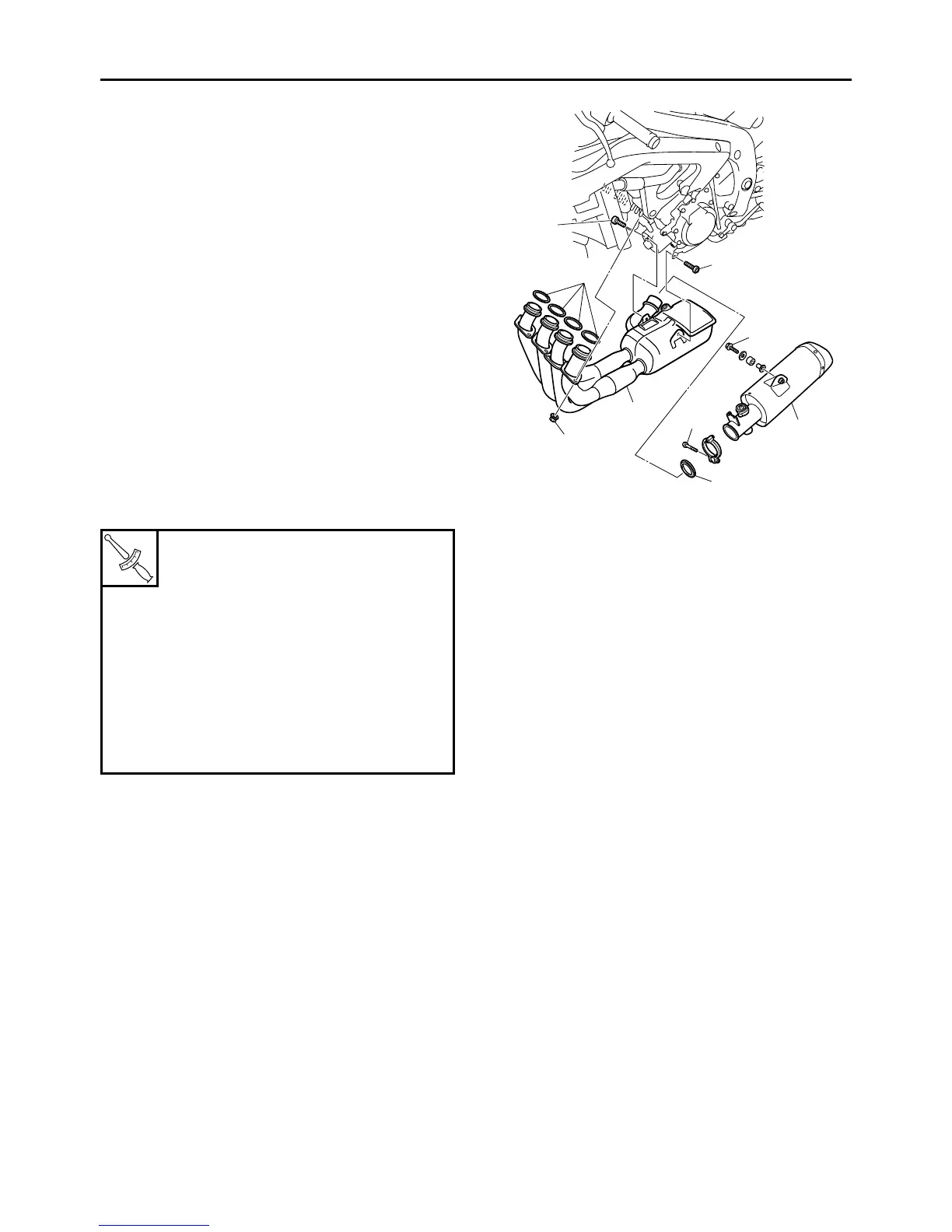
CHECKING THE EXHAUST SYSTEM
The following procedure applies to all of the ex-
haust pipe assembly and gaskets.
1. Remove:
• Side cowlings
• Bottom cowlings
Refer to “GENERAL CHASSIS” on page 4-1.
2. Check:
• Exhaust pipe assembly “1”
• Muffler “2”
Cracks/damage → Replace.
• Gaskets “3”
Exhaust gas leaks → Replace.
3. Check:
Tightening torque
• Exhaust pipe assembly and cylinder head
nuts “4”
• Exhaust pipe assembly and exhaust pipe as-
sembly bracket bolts “5”
• Exhaust pipe assembly and muffler bolt “6”
• Muffler and right rider footrest bracket bolt “7”
4. Install:
• Bottom cowlings
• Side cowlings
Refer to “GENERAL CHASSIS” on page 4-1.
EAS21090
CHECKING THE CANISTER (for California
only)
1. Remove:
• Fuel tank
Refer to “FUEL TANK” on page 7-1.
• Air filter case
Refer to “AIR FILTER CASE” on page 7-5.
2. Check:
• Canister
• Canister purge hoses
• 3-way joint
• Fuel tank breather hose (rollover valve to
canister)
Cracks/damage → Replace.
Refer to “THROTTLE BODIES” on page 7-8.
3. Install:
• Air filter case
Refer to “AIR FILTER CASE” on page 7-5.
• Fuel tank
Refer to “FUEL TANK” on page 7-1.
EAS21100
ADJUSTING THE EXUP CABLES
1. Remove:
• EXUP valve pulley cover “1”
T
R
.
.
Exhaust pipe assembly and cylin-
der head nut
20 Nm (2.0 m·kg, 14 ft·lb)
Exhaust pipe assembly and ex-
haust pipe assembly bracket bolt
20 Nm (2.0 m·kg, 14 ft·lb)
Exhaust pipe assembly and muf-
fler bolt
10 Nm (1.0 m·kg, 7.2 ft·lb)
Muffler and right rider footrest
bracket bolt
20 Nm (2.0 m·kg, 14 ft·lb)
2
3
1
(8)
3
7
6
4
5
5
 Loading...