CAMSHAFTS
5-9
EAS23810
REMOVING THE CAMSHAFTS
1. Remove:
• Pickup rotor cover
Refer to “PICKUP ROTOR” on page 5-30.
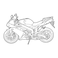
2. Align:
• TDC mark on the pickup rotor
(with the crankcase mating surface)
▼▼▼▼ ▼ ▼▼▼▼▼▼▼▼▼ ▼ ▼▼▼▼ ▼ ▼▼▼▼ ▼ ▼▼▼▼▼▼▼
a. Turn the crankshaft clockwise.
b. When piston #1 is at TDC on the compres-
sion stroke, align the TDC mark “a” on the
pickup rotor with the crankcase mating sur-
face “b”.
NOTE:
TDC on the compression stroke can be found
when the camshaft lobes are turned away from
each other.
▲▲▲▲ ▲ ▲▲▲▲▲▲▲▲▲ ▲ ▲▲▲▲ ▲ ▲▲▲▲ ▲ ▲▲▲▲▲▲▲
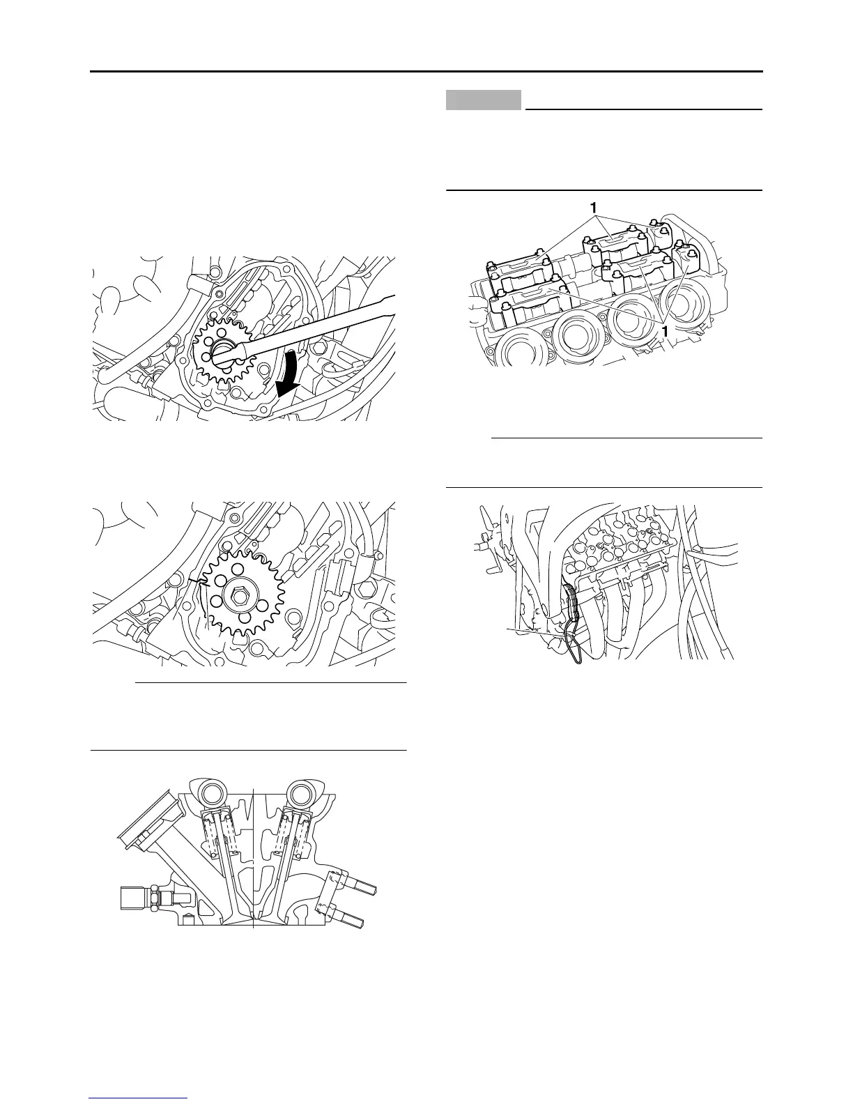
3. Remove:
• Camshaft caps “1”
CAUTION:
ECA13720
To prevent damage to the cylinder head,
camshafts or camshaft caps, loosen the
camshaft cap bolts in stages and in a criss-
cross pattern, working from the outside in.
4. Remove:
• Intake camshaft
• Exhaust camshaft
NOTE:
To prevent the timing chain from falling into the
crankcase, fasten it with a wire “1”.
EAS23850
CHECKING THE CAMSHAFTS
1. Check:
• Camshaft lobes
Blue discoloration/pitting/scratches → Re-
place the camshaft.
2. Measure:
• Camshaft lobe dimensions “a” and “b”
Out of specification → Replace the camshaft.
a
b
EXIN
11

 Loading...