ENGINE
3-4
EAS20470
ENGINE
EAS20490
ADJUSTING THE VALVE CLEARANCE
The following procedure applies to all of the
valves.
NOTE:
• Valve clearance adjustment should be made
on a cold engine, at room temperature.
• When the valve clearance is to be measured or
adjusted, the piston must be at top dead center
(TDC) on the compression stroke.
1. Remove:
• Rider seat
• Side cowlings
• Bottom cowlings
Refer to “GENERAL CHASSIS” on page 4-1.
• Fuel tank
Refer to “FUEL TANK” on page 7-1.
• Air filter case
Refer to “AIR FILTER CASE” on page 7-5.
• Canister (for California only)
Refer to “THROTTLE BODIES” on page 7-8.
• Throttle body
Refer to “THROTTLE BODIES” on page 7-8.
• Air cut-off valve
Refer to “AIR INDUCTION SYSTEM” on
page 7-15.
• Radiator
Refer to “RADIATOR” on page 6-1.
2. Remove:
• Ignition coils
• Spark plugs
• Cylinder head cover
Refer to “CAMSHAFTS” on page 5-7.
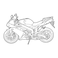
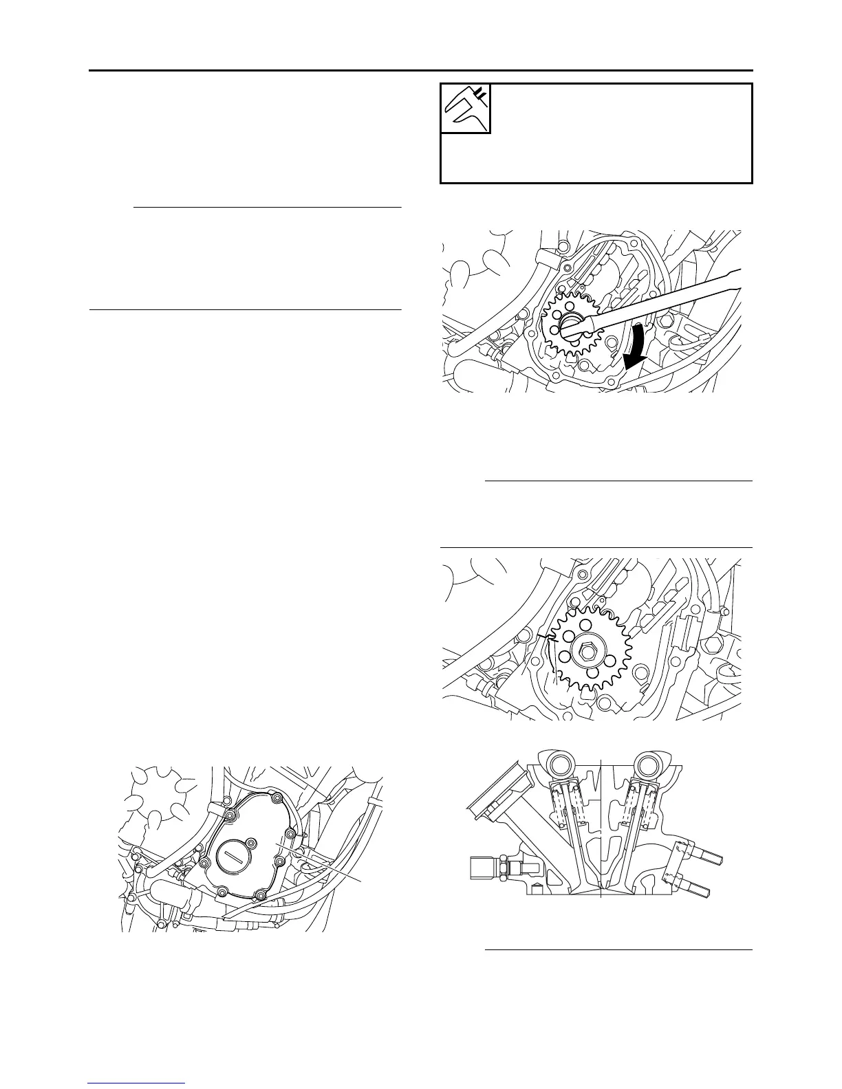
3. Remove:
• Pickup rotor cover “1”
4. Measure:
• Valve clearance
Out of specification → Adjust.
▼▼▼▼ ▼ ▼▼▼▼▼▼▼▼▼ ▼ ▼▼▼▼ ▼ ▼▼▼▼ ▼ ▼▼▼▼ ▼▼▼
a. Turn the crankshaft clockwise.
b. When piston #1 is at TDC on the compres-
sion stroke, align the TDC mark “a” on the
pickup rotor with the crankcase mating sur-
face “b”.
NOTE:
TDC on the compression stroke can be found
when the camshaft lobes are turned away from
each other.
c. Measure the valve clearance with a thickness
gauge “1”.
NOTE:
• If the valve clearance is incorrect, note the
measured reading.
1
Valve clearance (cold)
Intake
0.12–0.19 mm (0.0047–0.0075 in)
Exhaust
0.16–0.23 mm (0.0063–0.0091 in)
a
b
EXIN
 Loading...