ELECTRICAL COMPONENTS
8-96
• Fuel sender coupler
(from the wire harness)
2. Remove:
• Fuel tank
3. Remove:
• Fuel pump
(from the fuel tank)
4. Check:
• Fuel sender resistance
▼▼▼▼ ▼ ▼▼▼▼▼▼▼▼▼ ▼ ▼▼▼▼ ▼ ▼▼▼▼ ▼ ▼▼▼▼▼▼▼
a. Connect the pocket tester (Ω × 1) to the fuel
sender terminal as shown.
b. Measure the fuel sender resistance.
▲▲▲▲ ▲ ▲▲▲▲▲▲▲▲▲ ▲ ▲▲▲▲ ▲ ▲▲▲▲ ▲ ▲▲▲▲▲▲▲
EAS28240
CHECKING THE SPEED SENSOR
1. Check:
• Speed sensor output voltage
Out of specification → Replace.
▼▼▼▼ ▼ ▼▼▼▼▼▼▼▼▼ ▼ ▼▼▼▼ ▼ ▼▼▼▼ ▼ ▼▼▼▼▼▼▼
a. Connect the pocket tester (DC 20 V) to the
speed sensor coupler (wire harness side) as
shown.
b. Turn the main switch to “ON”.
c. Elevate the rear wheel and slowly rotate it.
d. Measure the voltage of white/yellow and
black/blue. With each full rotation of the rear
wheel, the voltage reading should cycle from
0.6 V to 4.8 V to 0.6 V to 4.8 V.
▲▲▲▲ ▲ ▲▲▲▲▲▲▲▲▲ ▲ ▲▲▲▲ ▲ ▲▲▲▲ ▲ ▲▲▲▲ ▲▲▲
EAS28250
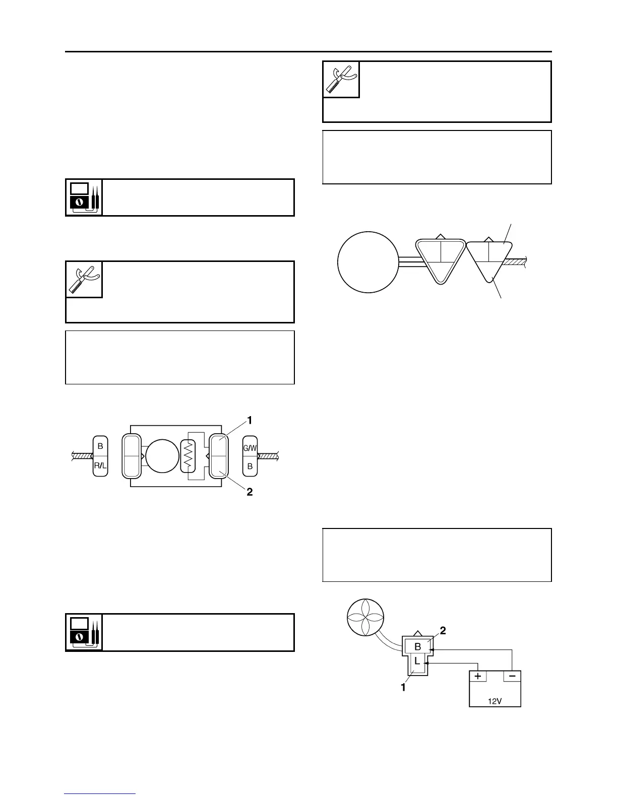
CHECKING THE RADIATOR FAN MOTORS
1. Check:
• Radiator fan motor
Faulty/rough movement → Replace.
▼▼▼▼ ▼ ▼▼▼▼▼▼▼▼▼ ▼ ▼▼▼▼ ▼ ▼▼▼▼ ▼ ▼▼▼▼ ▼▼▼
a. Disconnect the radiator fan motor coupler
from the wire harness.
b. Connect the battery (DC 12 V) as shown.
c. Measure the radiator fan motor movement.
▲▲▲▲ ▲ ▲▲▲▲▲▲▲▲▲ ▲ ▲▲▲▲ ▲ ▲▲▲▲ ▲ ▲▲▲▲ ▲▲▲
Fuel sender resistance
900–1050 Ω at 25 °C (77 °F)
Pocket tester
90890-03112
Analog pocket tester
YU-03112-C
• Positive tester probe →
green/white “1”
• Negative tester probe →
black “2”
Output voltage reading cycle
0.6 V to 4.8 V to 0.6 V to 4.8 V
Pocket tester
90890-03112
Analog pocket tester
YU-03112-C
• Positive tester probe →
white/yellow “1”
• Negative tester probe →
black/blue “2”
• Positive tester probe →
blue “1”
• Negative tester probe →
black “2”
LP
B
/
W
/
Y
L
1
2
B
/
W
O
/
R
 Loading...