ELECTRICAL COMPONENTS
8-93
d. Crank the engine by pushing the start switch
“” and gradually increase the spark gap un-
til a misfire occurs.
▲▲▲▲ ▲ ▲▲▲▲▲▲▲▲▲ ▲ ▲▲▲▲ ▲ ▲▲▲▲ ▲ ▲▲▲▲▲▲▲
EAS28120
CHECKING THE CRANKSHAFT POSITION
SENSOR
1. Disconnect:
• Crankshaft position sensor coupler
(from the wire harness)
2. Check:
• Crankshaft position sensor resistance
Out of specification → Replace the crank-
shaft position sensor.
▼▼▼▼ ▼ ▼▼▼▼▼▼▼▼▼ ▼ ▼▼▼▼ ▼ ▼▼▼▼ ▼ ▼▼▼▼▼▼▼
a. Connect the pocket tester (Ω × 100) to the
crankshaft position sensor coupler as shown.
b. Measure the crankshaft position sensor re-
sistance.
▲▲▲▲ ▲ ▲▲▲▲▲▲▲▲▲ ▲ ▲▲▲▲ ▲ ▲▲▲▲ ▲ ▲▲▲▲▲▲▲
EAS28130
CHECKING THE LEAN ANGLE SENSOR
1. Remove:
• Lean angle sensor
(from the bracket)
2. Check:
• Lean angle sensor output voltage
Out of specification → Replace.
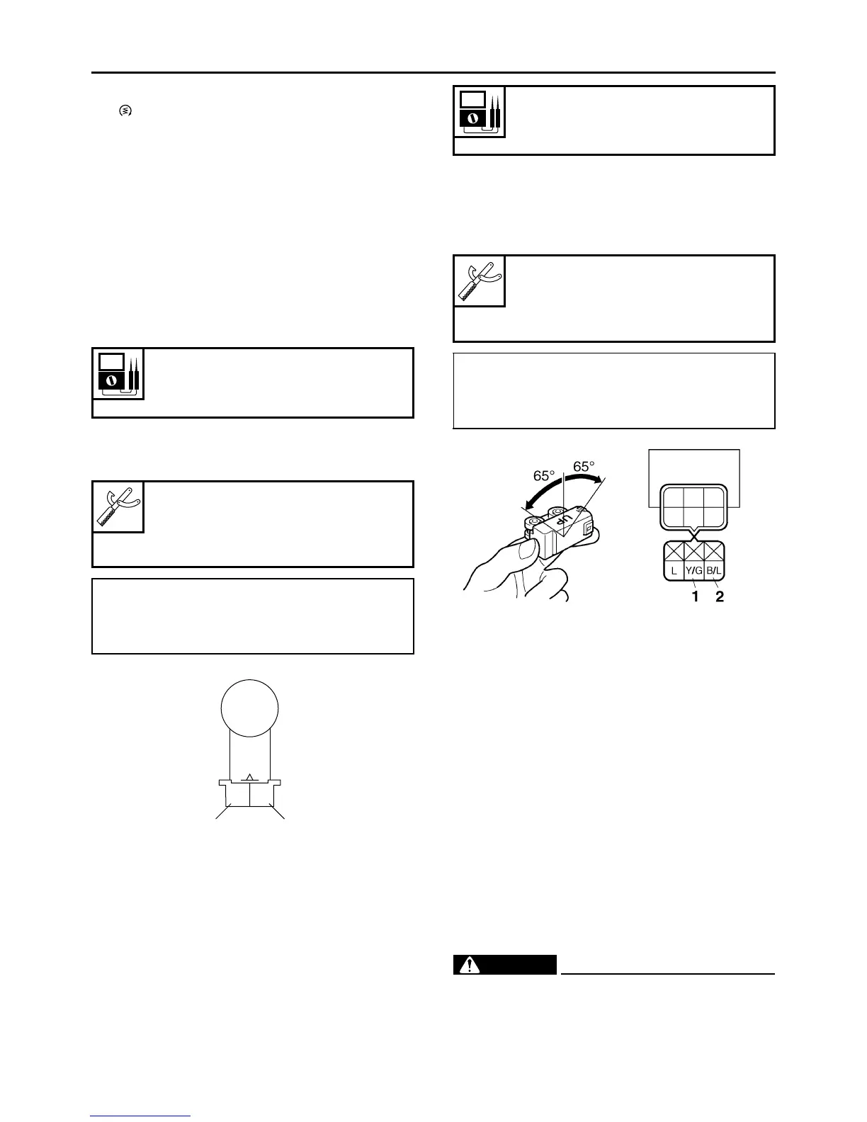
▼▼▼▼ ▼ ▼▼▼▼▼▼▼▼▼ ▼ ▼▼▼▼ ▼ ▼▼▼▼ ▼ ▼▼▼▼ ▼▼▼
a. Connect the lean angle sensor coupler to the
lean angle sensor.
b. Connect the pocket tester (DC 20 V) to the
lean angle sensor coupler as shown.
c. Turn the main switch to “ON”.
d. Turn the lean angle sensor to 65°.
e. Measure the lean angle sensor output volt-
age.
▲▲▲▲ ▲ ▲▲▲▲▲▲▲▲▲ ▲ ▲▲▲▲ ▲ ▲▲▲▲ ▲ ▲▲▲▲ ▲▲▲
ET2C01012
CHECKING THE STARTER MOTOR
OPERATION
1. Check:
• Starter motor operation
Does not operate → Perform the electric
starting system troubleshooting, starting with
step 4.
Refer to “TROUBLESHOOTING” on page
8-11.
▼▼▼▼ ▼ ▼▼▼▼▼▼▼▼▼ ▼ ▼▼▼▼ ▼ ▼▼▼▼ ▼ ▼▼▼▼ ▼▼▼
a. Connect the positive battery terminal “1” and
starter motor lead “2” with a jumper lead “3”.
WARNING
EWA13810
• A wire that is used as a jumper lead must
have at least the same capacity of the bat-
tery lead, otherwise the jumper lead may
burn.
Crankshaft position sensor resis-
tance
248–372 Ω at 20 °C (68 °F)
Pocket tester
90890-03112
Analog pocket tester
YU-03112-C
• Positive tester probe →
gray “1”
• Negative tester probe →
black “2”
Gy
B
12
Lean angle sensor output voltage
Less than 65°: 0.4–1.4 V
More than 65°: 3.7–4.4 V
Pocket tester
90890-03112
Analog pocket tester
YU-03112-C
• Positive tester probe →
yellow/green “1”
• Negative tester probe →
black/blue “2”

 Loading...