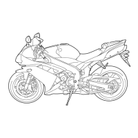
FRONT BRAKE
4-23
d. Measure the brake disc deflection.
e. If out of specification, repeat the adjustment
steps until the brake disc deflection is within
specification.
f. If the brake disc deflection cannot be brought
within specification, replace the brake disc.
▲▲▲▲ ▲ ▲▲▲▲▲▲▲▲▲ ▲ ▲▲▲▲ ▲ ▲▲▲▲ ▲ ▲▲▲▲▲▲▲
6. Install:
• Front wheel
Refer to “FRONT WHEEL” on page 4-4.
EAS22270
REPLACING THE FRONT BRAKE PADS
The following procedure applies to both brake
calipers.
NOTE:
When replacing the brake pads, it is not neces-
sary to disconnect the brake hose or disassem-
ble the brake caliper.
1. Measure:
• Brake pad wear limit “a”
Out of specification → Replace the brake
pads as a set.
2. Install:
• Brake pads
• Brake pad spring
NOTE:
Always install new brake pads, and a brake pad
spring as a set.
▼▼▼▼ ▼ ▼▼▼▼▼▼▼▼▼ ▼ ▼▼▼▼ ▼ ▼▼▼▼ ▼ ▼▼▼▼ ▼▼▼
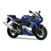
a. Connect a clear plastic hose “1” tightly to the
bleed screw “2”. Put the other end of the hose
into an open container.
b. Loosen the bleed screw and push the brake
caliper pistons into the brake caliper with your
finger.
c. Tighten the bleed screw.
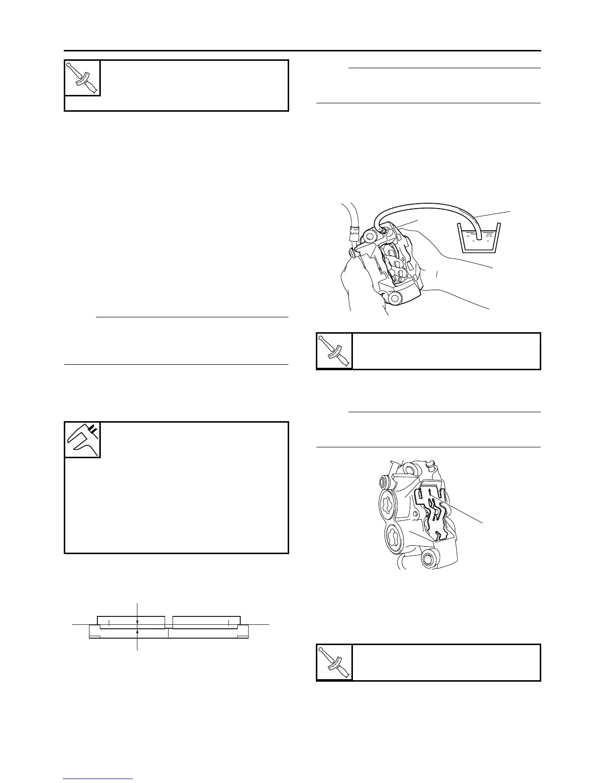
d. Install new brake pads and a new brake pad
spring.
NOTE:
The arrow mark “a” on the brake pad spring
must point in the direction of disc rotation.
▲▲▲▲ ▲ ▲▲▲▲▲▲▲▲▲ ▲ ▲▲▲▲ ▲ ▲▲▲▲ ▲ ▲▲▲▲ ▲▲▲
3. Install:
• Brake pad pin
• Brake pad clips
• Front brake caliper
4. Check:
• Brake fluid level
Below the minimum level mark “a” → Add the
recommended brake fluid to the proper level.
T
R
.
.
Brake disc bolt
18 Nm (1.8 m·kg, 13 ft·lb)
LOCTITE
®
Brake pad lining thickness (in-
ner)
4.5 mm (0.18 in)
Limit
0.5 mm (0.02 in)
Brake pad lining thickness (out-
er)
4.5 mm (0.18 in)
Limit
0.5 mm (0.02 in)
a
T
R
.
.
Bleed screw
5 Nm (0.5 m·kg, 3.6 ft·lb)
T
R
.
.
Brake caliper bolt
35 Nm (3.5 m·kg, 25 ft·lb)
2
1
a
 Loading...