CONNECTING RODS AND PISTONS
5-64
▲▲▲▲ ▲ ▲▲▲▲▲▲▲▲▲ ▲ ▲▲▲▲ ▲ ▲▲▲▲ ▲ ▲▲▲▲▲▲▲
2. Select:
• Big end bearings (P
1
–P
4
)
NOTE:
• The numbers stamped into the crankshaft web
and the numbers on the connecting rods are
used to determine the replacement big end
bearing sizes.
• P
1
–P
4
refer to the bearings shown in the crank-
shaft illustration.
For example, if the connecting rod P
1
and the
crankshaft web P
1
numbers are 5 and 1 re-
spectively, then the bearing size for P
1
is:
EAS26170
INSTALLING THE CONNECTING RODS AND
PISTONS
The following procedure applies to all of the pis-
tons and connecting rods.
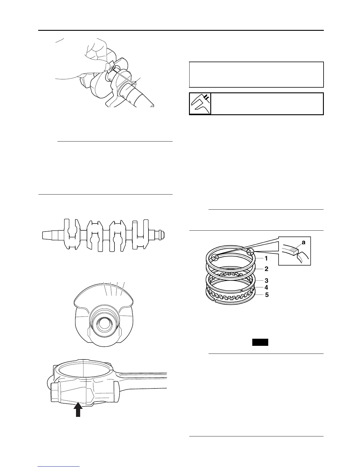
1. Install:
• Top ring “1”
• 2nd ring “2”
• Upper oil ring rail “3”
• Oil ring expander “4”
• Lower oil ring rail “5”
NOTE:
Be sure to install the piston rings so that the
manufacturer’s marks or numbers “a” face up.
2. Install:
• Piston “1”
(onto the respective connecting rod “2”)
• Piston pin “3”
• Piston pin clips “4”
NOTE:
• Apply engine oil onto the piston pin.
• Make sure that the “Y” mark “a” on the connect-
ing rod left when the punch mark “b” on the pis-
ton is pointing up. Refer to the illustration.
• Install the piston pin clips, so that the clip ends
are 3 mm (0.12 in) “c” or more from the cutout
in the piston.
• Reinstall each piston into its original cylinder
(numbering order starting from the left: #1 to
#4).
e
P1
P2
P3
P4
2 1 1 2 2 1 1 1 1
P1 P2 P3 P4
5 F
P
1
(connecting rod) - P
1
(crankshaft)
=
5 - 1 = 4 (green)
Bearing color code
1.Blue 2.Black 3.Brown 4.Green
New

 Loading...