THROTTLE BODIES
7-13
ET2C01007
ADJUSTING THE THROTTLE POSITION
SENSOR (FOR THROTTLE VALVES)
1. Check:
• Throttle position sensor (for throttle valves)
Refer to “CHECKING THE THROTTLE PO-
SITION SENSOR (FOR THROTTLE
VALVES)” on page 8-97.
2. Adjust:
• Throttle position sensor angle
▼▼▼▼ ▼ ▼▼▼▼▼▼▼▼▼ ▼ ▼▼▼▼ ▼ ▼▼▼▼ ▼ ▼▼▼▼▼▼▼
a. Connect the two C size batteries to the throt-
tle servo motor terminal as shown.
CAUTION:
EC2C01027
Do not use a 12 V battery to operate the throt-
tle valves.
b. Check that the throttle valves are fully closed.
c. Connect the throttle position sensor coupler
to the throttle position sensor.
d. Connect the digital circuit tester to the throttle
position sensor.
e. Measure the throttle position sensor voltage.
f. Adjust the throttle position sensor angle so
that the voltage is within the specified range.
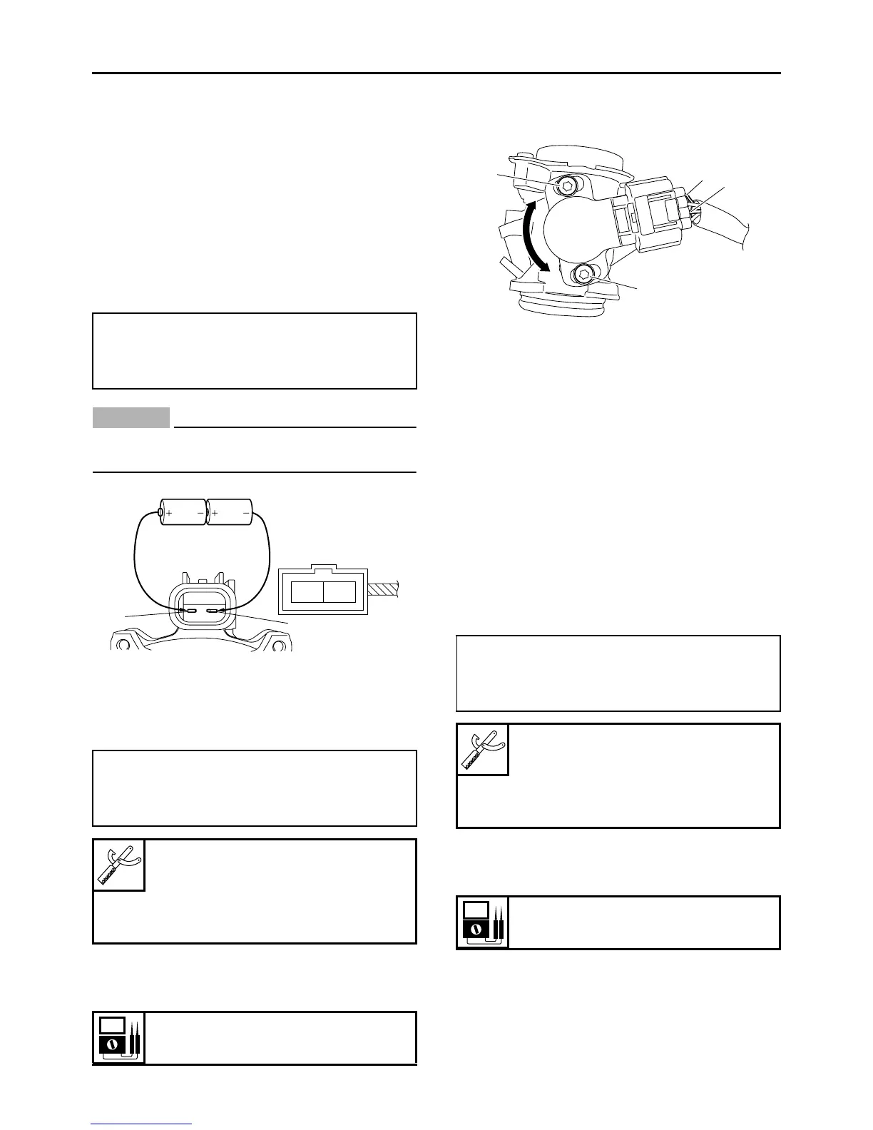
g. After adjusting the throttle position sensor an-
gle, tighten the throttle position sensor
screws “3”.
▲▲▲▲ ▲ ▲▲▲▲▲▲▲▲▲ ▲ ▲▲▲▲ ▲ ▲▲▲▲ ▲ ▲▲▲▲ ▲▲▲
ET2C01008
ADJUSTING THE THROTTLE POSITION
SENSOR (FOR THROTTLE CABLE PULLEY)
1. Check:
• Throttle position sensor (for throttle cable pul-
ley)
Refer to “CHECKING THE THROTTLE PO-
SITION SENSOR (FOR THROTTLE CABLE
PULLEY)” on page 8-98.
2. Adjust:
• Throttle position sensor angle
▼▼▼▼ ▼ ▼▼▼▼▼▼▼▼▼ ▼ ▼▼▼▼ ▼ ▼▼▼▼ ▼ ▼▼▼▼ ▼▼▼
a. Connect the throttle position sensor coupler
to the throttle position sensor.
b. Connect the digital circuit tester to the throttle
position sensor.
c. Measure the throttle position sensor voltage.
d. Adjust the throttle position sensor angle so
that the voltage is within the specified range.
e. After adjusting the throttle position sensor an-
gle, tighten the throttle position sensor
screws “3”.
• Positive battery lead
light green/red terminal “1”
• Negative battery lead
yellow/red terminal “2”
• Positive tester probe
white terminal “1”
• Negative tester probe
black/blue terminal “2”
Digital circuit tester
90890-03174
Model 88 Multimeter with ta-
chometer
YU-A1927
Output voltage
0.635–0.645 V
Lg/R
Y/B
1
2
• Positive tester probe
blue terminal “1”
• Negative tester probe
black/blue terminal “2”
Digital circuit tester
90890-03174
Model 88 Multimeter with ta-
chometer
YU-A1927
Output voltage
0.630–0.730 V
3
3
2
1

 Loading...