5-6
IM 04L51B01-01EN
5.1.3 Performing A/D Calibration and Adjusting the Input Accuracy of AI
Modules
Preparing the Instruments
1
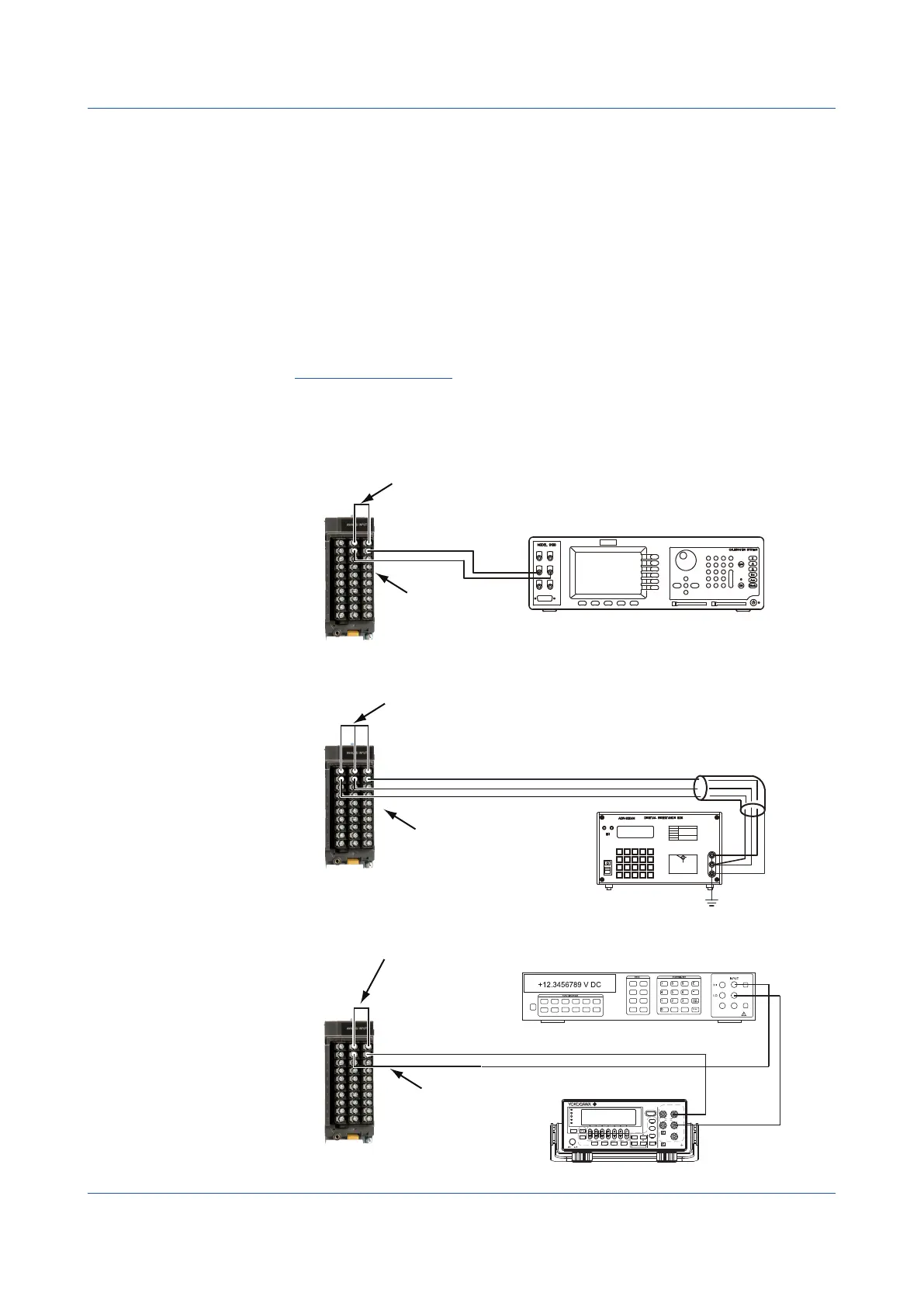
Wire the GX/GP and the calibration instruments as shown in the following figure, and
adequately warm up the instruments (the warm-up time of the GX/GP is at least 30
minutes).
For details on wiring, see “Installation and Wiring” in the First Step Guide (IM 04L51B01-02EN).
2
Check that the operating environment such as ambient temperature and humidity is
within the standard operating conditions (see “General Specifications”).
Operation complete
Universal,ElectromagneticRelay,LowWithstandVoltageRelay,Current(mA),4-wire
RTD/Resistance Type
Wiring for DC voltage range
Wiring for RTD range
CH1
CH2
CH1
CH2
+
–
DC voltage/current standard
Hi
Lo
Make the resistance of three lead wires equal.
b
A
Resistance standard
H
L
G
B
A
B
b
Short the input terminal of CH1 (apply 0 V)
Short the input terminal of CH1 (connect 0 Ω)
Input terminal of CH2
Input terminal of CH2
CH1
CH2
Short the input terminal of CH1 (supply 0 A)
Wiring Current (mA) Input Modules
Input terminal of CH2
+
–
GS200
DC VOLTAGE/CURRENT SOURCE
SAMPLE
ERROR
REPEAT
STORE
REMOTE
ERROR
LOCAL
ESC
POWER
NUM
LOCK
1 2 3 4 5
BS
RANGE
6 7 8 9 0
UTILITY
SETUP
LIMIT
MEASURE
PROGRAM
END
DEL
HOLD
STEP
RUN
PROGRAM
OUTPUT
V
mV
mA
SRQ
ENTER
SENSE OUTPUT
32V
MAX
0.5V
MAX
32V
200mA
MAX
Hi
Lo
42V
10mA
PEAK
G
G TERM 250 V PEAK TO
DC current source
Digital multimeter
.
5.1 Maintenance

 Loading...