App-31
IM 04L51B01-01EN
Appendix
App
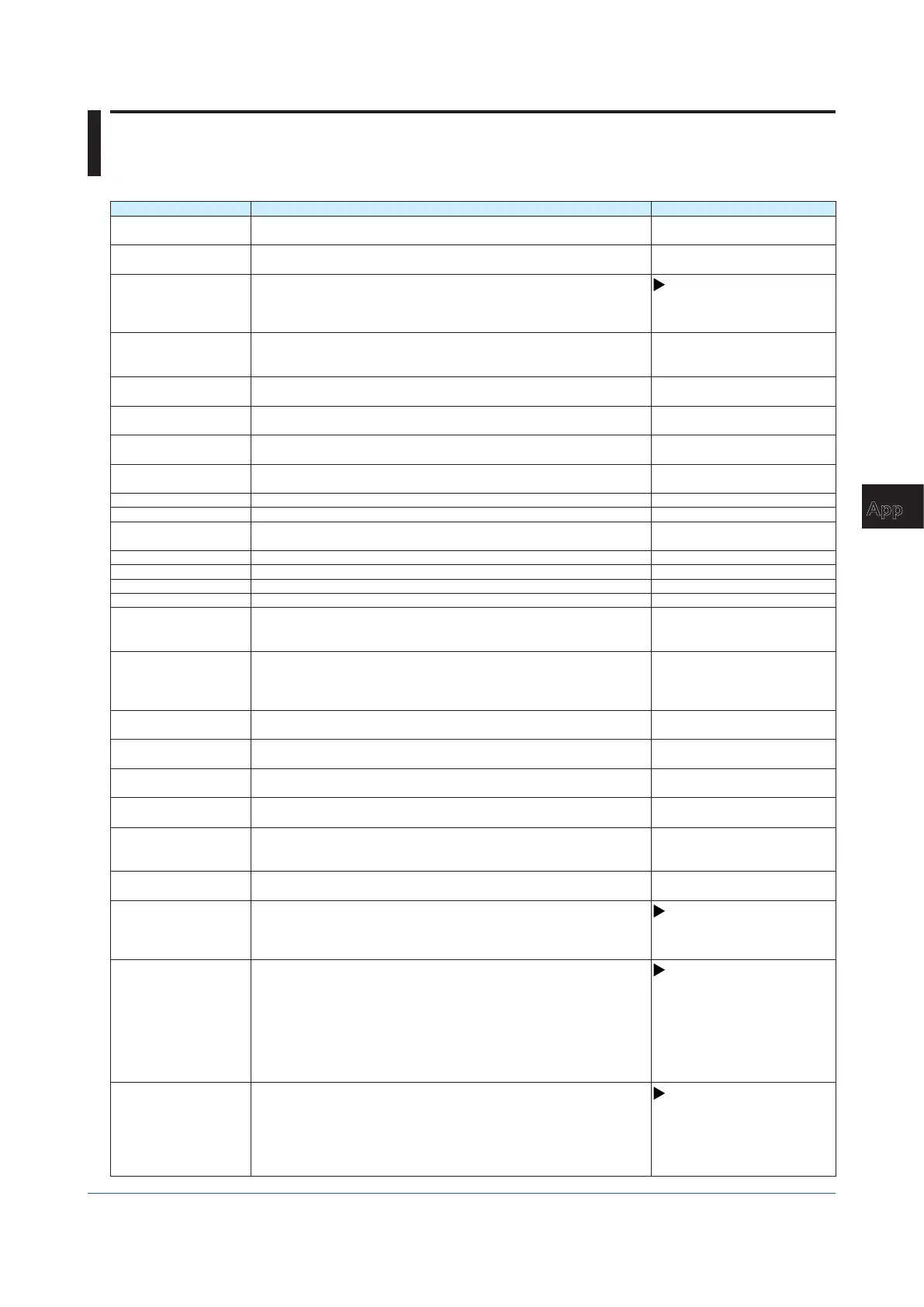
Appendix 8 Terminology
This section explains the terminology related to the GX/GP.
Term Explanation Notes
Display data Waveform data that is displayed on the GX/GP screen. It is a recording
of measured data sampled at the display data sampling interval.
Event data Event data is a recording of measured data at a specified recording
interval. This is separate from the display data.
Trend interval The interval at which the waveform display is updated. The display is
updated at a time interval that corresponds to 1 dot, which is determined
by the specified recording interval (time interval that corresponds to 1
division).
See page 1-110 in section
1.10.1, “Setting the Trend
Interval”
I/O channel A collective term that refers to analog input channels (AI channels),
digital input channels (DI channels), and digital output channels (DO
channels).
AI channel Analog input channel. Analog input channels can receive and measure
DC voltage, thermocouple (TC), RTD, and On/Off signals (DI).
DI channel Digital input channel. Digital input channels can measure On/Off
signals.
AO channel Analog output channel. These channels can output DC current signals
(4-20mA, 0-20mA range).
DO channel Digital output channel. Digital output channels can be used as relay
outputs.
PID channel A channel (PV, SP, OUT, AI, DI, AO, or DO) on a PID control module.
GS (range type) Range type for 1-5VDC and 0.4-2VDC signals
GS (4-20mA) (range
type)
Range type for 4 to 20 mADC signals (current input modules)
DI (range type) Range type for digital input (1, 0) based on contacts or voltage levels
RTD (range type) Range type for RTD sensors
TC (range type) Range type for thermocouple sensors
Resistance (range type) This is a range type for the 4-wire resistance input.
Input calculation Calculation performed on inputs, such as scaling, taking the difference
between two channels (difference in relation to a reference channel),
and square rooting.
Historical trend Waveform based on past measured data as opposed to the waveform
based on current data. The waveform display area of historical trends
shown from a memory summary, message summary, alarm summary
and so on is displayed in gray.
Color scale band Displays a specified section (inside or outside) of the measurement
range using a color band on the scale.
Trip line A line displayed at a specified position in the waveform display range on
the trend display.
Zone (display) Zones enable channels to be displayed in separate areas so that
waveforms do not overlap.
Partial expanded display Partial expanded display compresses a section of the waveform display
range so that the rest of the section is expanded.
Manual sample An action executed through a screen operation or event action function.
The action saves instantaneous values of all channels (except those set
to Skip or Off).
Snapshot An image of the GX/GP screen saved in PNG format to an SD memory
card. Some screens cannot be saved as screenshots.
Reconfiguration A system reconfiguration that aligns the GX/GP settings to the I/O
module configuration.
Reconfiguration is necessary when the positions of different types of
modules are changed and when modules are added or deleted.
See page 1-256 in section
1.29.4, “Reconfiguring the GX/
GP”
Individual alarm ACK The operation of acknowledging alarms (clearing alarm output)
separately by channel and level.
See page 1-205 in section
1.23.3, “Setting the Alarm
Display Hold/Nonhold
and Individual Alarm ACK
Operation”, page 2-65 in section
2.4.1, “Releasing Alarm Output
(Alarm ACK and individual alarm
ACK operation)”
General communication
(GENE)
A function for communicating with the GX/GP (configuration and control)
using GX/GP dedicated communication commands.
See page 1-194 in section
1.21.9, “Setting the Server
Functions to Use (FTP,
HTTP, SNTP, MODBUS,
GENE, DARWIN compatible
communication)”

 Loading...