1-79
IM 04L51B01-01EN
Configuring the GX/GP and Viewing the Settings
1
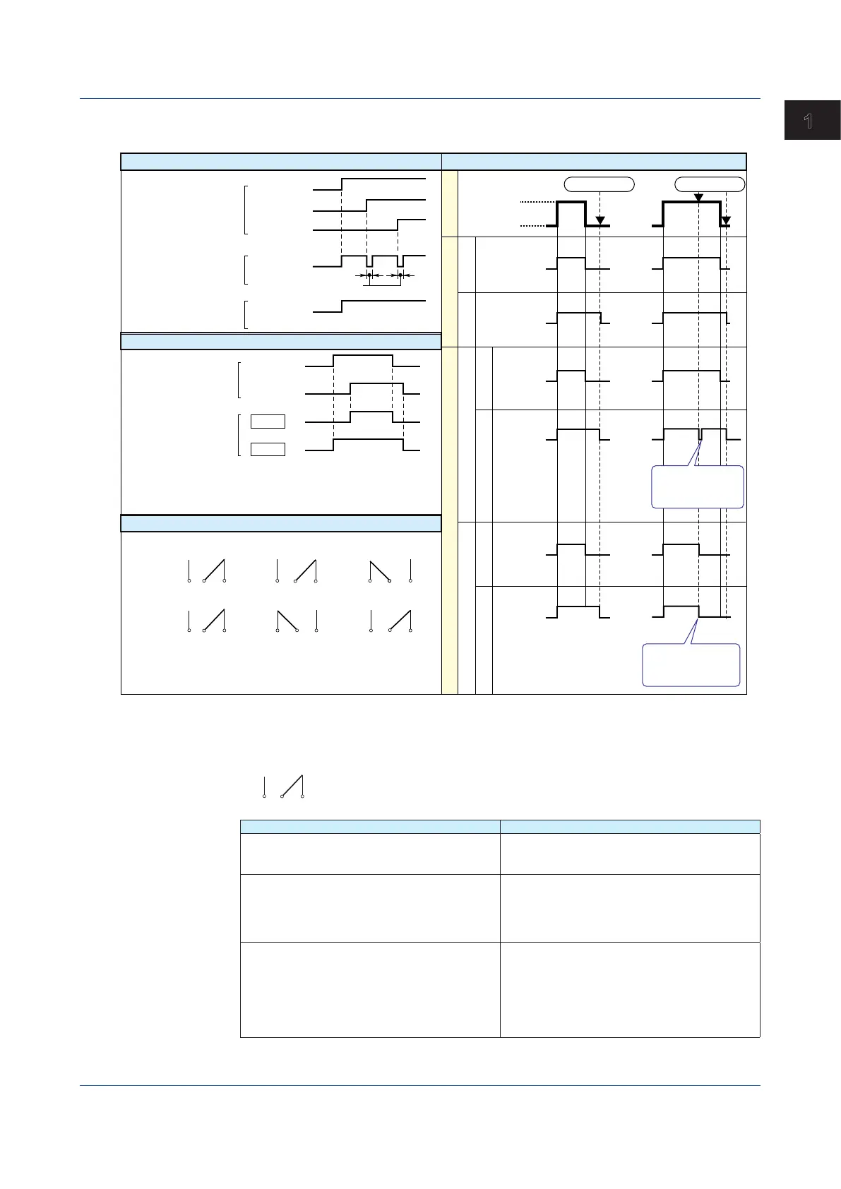
DO Output Relay Operation
The DO output relay operation is shown below.
Alarm
DO output relay
(Reflash on)
DO output relay
(Reflash off)
Channel 1
Channel 3
Channel 2
500 ms, 1 s, 2 s
Energize or De-energize
AND/OR
Alarm
Channel 1
AND
Channel 2
OR
DO output relay
or
Internal switch
NO
Energize
De-energize
C NC NO C NC NO C NC
NO C NC NO C NCNO C NC
When power is
shut down
NO: Normally Opened
C: Common
Normal
operation
When an alarm
is occurring
Alarm
Normal
Alarm
Normal
Reflash
(You can set AND/OR for the DO output relay and
internal switch.)
(when a relay is set to OR logic)
Normal
Reset
Relay action on ACK
Relay action on ACK
occurrence
Activated
Deactivated
Activated
Deactivated
Activated
Deactivated
release
Activated
Deactivated
Display Alarm
Hold
Non-hold
DO output relay
Hold
Non-hold
Hold
Non-hold
Non-hold/Hold
Relay is activated
after 100 ms.
Relay is deactivated
until the next
alarm occurs.
Alarm ACKAlarm ACK
DOOutputRelayOperationduringanError
When an error (FAIL) occurs in the system, the DO output relay is de-energized (as shown
below). The DO output relay operation is shown below.
Item Description
When a CPU error occurs in the GX/GP The DO output relay of the GX/GP is de-energized.
The DO output relays of all expandable I/Os are
de-energized.
When a CPU error occurs in an expansion module The DO output relays of the GX/GP and
expandable I/Os in which errors are not occurring
continue normal operation.
The DO output relay of the expandable I/O in
which the error occurred is de-energized.
When a connection between expandable I/Os are
disconnected
The DO output relay of the GX/GP continues
normal operation.
The DO output relays of the expandable I/O that
was disconnected and those of subsequent units
are de-energized.
Normal operation resumes when the connection
recovers.
1.6ConfiguringDOChannels(Digitaloutputchannels)

 Loading...