12-2
VARIABLE MOWING SYSTEM/ MOWER DECK/WHEELS HRX217HYA • HRX217HZA
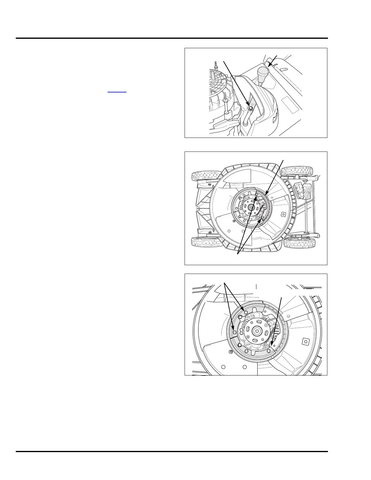
1. VARIABLE MOWING SYSTEM
SHUTTER LEVER REMOVAL/INSTALLATION
REMOVAL
1.Remove fan cover/fuel tank (P. 8-14).
2.Move shutter lever to the mulch position.
3.Remove the 6 x 8 mm flange bolt that mounts the lever
to the arm.
4.Remove the shutter lever.
Installation is done in the reverse order of removal.
SHUTTER REMOVAL/INSTALLATION
REMOVAL
1. Remove the two rear 5/16-24 x 2-3/8 inch engine
mounting bolts and the rear shutter holder.
2. Remove the four 8 x 10 mm flange bolts and the two
front shutter holders.
LEVER
FLANGE BOLT,
6 x 8 mm
BOLT, 5/16-24 x 2-3/8 in (2)
REAR SHUTTER HOLDER
FLANGE BOLT, 8 x 10 mm (4)
FRONT SHUTTER HOLDER (2)

 Loading...