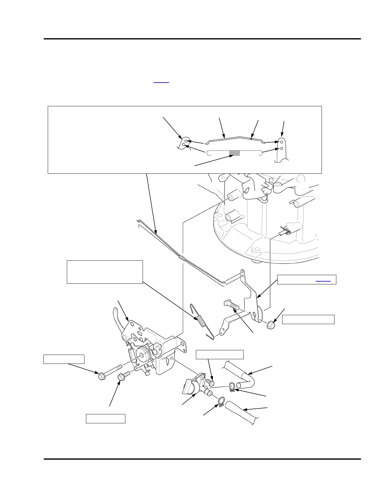
2. CONTROL BASE/GOVERNOR ARM
INSTALLATION:
Install with the short end side
toward the governor arm.
2.5 N·m (1.8 ft-lb)
GOVERNOR SPRING
SCREW (5 x 10 mm)
GOVERNOR ARM BOLT
GOVERNOR ARM NUT
3 N·m (2.2 ft-lb) min.
FUEL VALVE
B12 TUBE CLIP
B8 TUBE CLIP
BOLT (CT bolt ; 6 x 14 mm)
CONTROL BASE
FUEL TUBE
GOVERNOR ARM
INSTALLATION:
Install the governor rod through the
throttle return spring as shown.
Connect each to the governor arm and
carburetor throttle arm as shown.
GOVERNOR ARM/THROTTLE RETURN SPRING
THROTTLE ARM GOVERNOR ROD
GOVERNOR
ARM
THROTTLE RETURN SPRING
12 N·m (9 ft-lb)
PAINT
FUEL TUBE
BOLT (CT bolt ; 6 x 50 mm)
12 N·m (9 ft-lb)
ADJUSTMENT: P. 3-17

 Loading...