SV-DA200 series AC servo drive Function codes
-100-
Numerator of 1
st
electronic gear ratio
Denominator of the
electronic gear ratio
Numerator of 2
nd
electronic gear ratio
Numerator of 3
rd
electronic gear ratio
Numerator of 4
th
electronic gear ratio
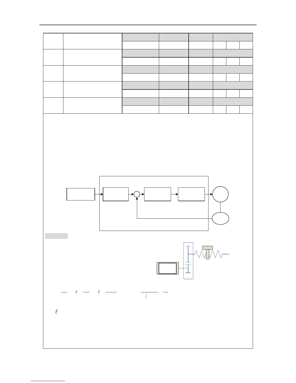
Concept of the electronic gears: for any pulse input, the number and frequency of the pulse
actually received by the drive can be changed by multiplying a certain coefficient and this
coefficient is electronic gear ratio. It can be indicated in two parts: numerator and denominator:
Electronic gear ratio = g1/ g2;
Of which
g1: The numerator of the electronic gear ratio;
g2: The denominator of the electronic gear ratio;
Below is the schematic diagram of the electronic gear ratio in the system:
Deviation
counter
Motor
Encoder
Intermediate
link
Electrical gear
ratio
Input pulse train
Feedback pulse
Example: Below is a case where 1 pulse is
equivalent to a feed rate of 10μm
Mechanical specifications:
Feed of the ball screw Pb =10mm;
Reduction ratio n=3/5;
Resolution of the servo motor encoder =10000;
At this time calculate the electronic gear ratio:
3
00
1 10000 50
10 10
2 (3 5) 10 3
g Pt Pt
g S n Pb
· · ·
: Feed rate corresponding to each pulse (mm/pulse);
: Feed rate corresponding to each rotation of the motor (mm/rot).
i.e. in this example, g1=50, g2=3.
Set P0.25 to 50 and P0.26 to 3.
The servo drive has 4 groups of electric gear ratio: P0.25, P0.26, P0.27 and P0.28, P0.29 can
 Loading...
