Home
INVT
Servo Drives
SV-DA200 Series
INVT SV-DA200 Series User Manual
4
of 1
of 1 rating
300 pages
Give review
Manual
Specs
To Next Page
To Next Page
To Previous Page
To Previous Page
Loading...
SV
-
DA
2
00
ser
ies AC
servo dri
ve
Wiring
instru
ction
-
44
-
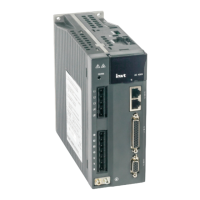
3.6 W
iring of 485/
CA
N-CN3 terminals
Pin8
Pin1
CN3 te
rminal funct
ion
Pin
Name
Functio
n
Remark
1
GND_CAN
CAN chip
pow
er GND
485 and
CAN use the
same in
terface and
each
signal ha
s tw
o pins for
multiple n
etw
orking.
2
GND_485
485 chip
pow
er GND
4
RS485+
RS485
data +
5
RS485-
RS485
data -
7
CAN_L
CAN da
ta -
8
CAN_H
CAN da
ta +
3, 6
-
Unused
Note:
EtherCAT bus-typ
e
drive
, t
his port is
standard
netw
ork c
able port definitio
n, namely pin
1, 2,
3
and 6 cor
respond
to Tx+, T
x-, Rx+
and Rx- re
spectively
.
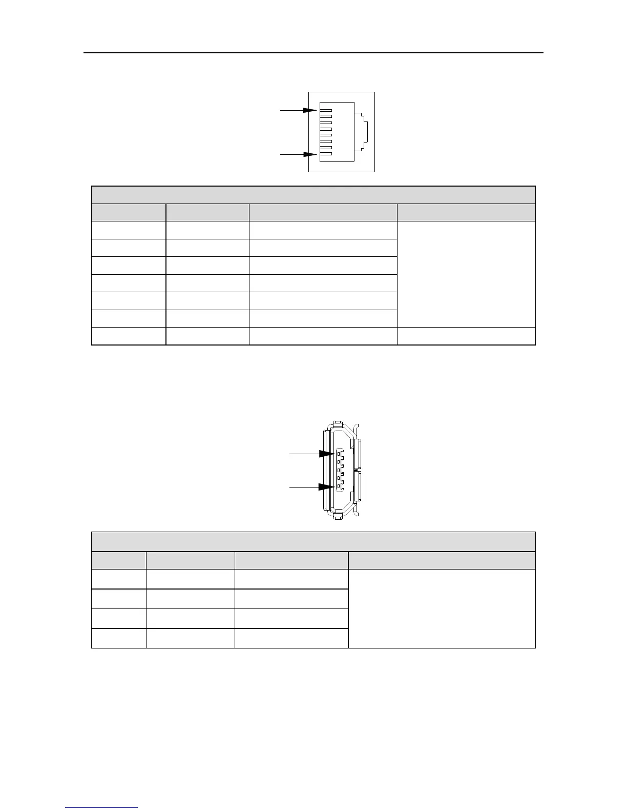
3.7 W
iring of U
SB-CN4 t
erminals
Pin
5
Pin
1
CN4 USB
port fun
ction
Pin
Name
Functio
ns
Remark
2
D-
Data -
The standar
d cable
for USB
micro to
USB-A c
onversion
is availab
le.
3
D+
Data +
5
GND
Signal gr
ound
1, 4
-
Unused
47
49
Table of Contents
Safety Precautions
3
Safety Symbols
3
Table of Contents
5
1 Product Overview
7
Servo Drive
7
Instruction to the Drive
7
External Appearance of the Drive
10
Standard Model
10
Naming of the Drive
11
Function Difference between Different Machine Types
12
Nameplate of the Drive
12
Medium-Power Range
12
Small Power Range
12
Power Ratings and Cabinet Volumes
13
Servo Motor
14
Nameplate of the Motor
14
Naming of the Servo Motor
14
Cables
16
Nameplate of Cables
16
Naming of the Power Cables
16
Naming of Power Cable Fitting
17
Naming of the Encoder Cables
18
Naming of Encoder Cables Fittings
19
Naming of Motor Braking Cables
19
Braking Resistor Specification
20
2 Installation Instruction
21
Drive Dimension
21
A/B/C Size and Dimension Diagram
21
Dimension Diagram for D Size
21
Dimension Diagram for F/F2 Size
22
Dimension Diagram for G Size
22
Dimension Diagram for H Size
22
Detailed Dimension Table
23
Drive Installation
24
Installation Mode
24
Installation Space and Direction
25
Single Drive Installation
25
Multiple Drives Installation
25
Motor Dimension
26
Outline and Installation Dimension for 40 Base
26
Outline and Installation Dimension for 60 Base (MM)
27
Outline and Installation Dimension for 80 Base (MM)
28
Outline and Installation Dimension for 110 Base (MM)
29
Outline and Installation Dimension for 130 Base (MM)
30
Outline and Installation Dimension for 180 Base (MM)
31
SV-SM18-7R5B Shaft Extension Dimension (MM)
31
Outline and Installation Dimension for 200 Base (MM)
32
Outline and Installation Dimension for 263 Base (MM)
32
Motor Installation
33
Technical Parameters of Servo Motor
33
Motor Specification
33
3 Wiring Instruction
36
System Wiring
36
Requirements on Input Power Cable
37
Four-Core Cable with Shielded Layer
37
Requirements on Control Cable
37
Multiple Double-Shielded Twisted Pairs
37
Cable Diameter of Main Circuit
38
EMI Filter
39
Terminal Wiring of the Main Circuit
40
Wiring Diagram of Single Phase 220V
40
Wiring Diagram of Three Phase 220V/400V
41
Wiring Diagram of Three Phase 400V
42
Wiring of Motor Power Cables
43
2500-PPR 40/60/80-Base 100W–750W Motor Power Cable
43
17-Bit or 23-Bit 40/60/80-Base 100W–750W Motor Power Cable
43
200/260-Base 11Kw–55Kw (380V) Motor Power Cable
44
130-Base 17-Bit Single-Turn Motor Power Cable with Brake
44
Control I/O-CN1 Terminal Layout
45
Wiring of Encoder-CN2 Terminals
45
CN1 Plug Pin Layout
45
CN1 Plug Signal Layout
45
2500-PPR 40, 60, 80-Base Encoder Cable
46
2500-PPR 110, 130, 180, 200 Base Encoder Cable
46
Wiring Relation
46
17-Bit and 23-Bit 40, 60, 80 Base Encoder Cable
47
17-Bit and 23-Bit 110, 130, 180, 200 Base Encoder Cable
47
Rotary Transformer Encoder Cable
47
Wiring of 485/CAN-CN3 Terminals
48
CN3 Terminal Function
48
CN4 USB Port Function
48
2Nd Encoder and STO-CN5 Terminal Wiring
49
Small Power Range CN5 Port Function
49
CN5 Terminal Function Table
49
Wiring of PROFIBUS-DP Terminals
50
DP Plug Pin Layout
50
DP Plug Signal Layout
50
Function of CN7 Port
51
4 Control Mode Applications
52
Standard Wiring of the Position Mode
52
Standard Wiring of the Speed Mode
53
Standard Wiring of the Torque Mode
54
CN1 Function Instruction
55
Pins of CN1 Terminal
55
Definition of CN1 Terminals
55
Power Supply Signal
56
Configuration Table for Different Digital Modes
56
Function Description of the Digital Input
58
Torque Mode
58
Servo Enabling
58
Alarm Clearing
58
Retention Pulse Clearing
59
Command Pulse Disabled
59
Torque Limit Switching
59
Zero Speed Clamp
59
Speed Command Sign
60
Torque Command Sign
60
Inertia Ratio Switching
61
Emergency Stop
61
HOME Switch Input
61
HOME Trigger
61
Vibration Control Switching Input
62
Fast Stop
62
PTP Control Stop
62
Forward Jogging
62
Gantry Synchronization Input Clear
63
Dynamic Braking Relay Feedback
63
Manual and Automatic Switching of Turret
63
Forward Jogging of Turret
63
Digital Output Instruction
64
Servo Ready Output
64
Servo Operation Output
64
Fault Output
64
Speed Reaching
65
Speed Limiting
65
Speed Command or Not
65
Speed Zero Output
65
PTP Output 2
66
PTP Output 3
66
Gantry Synchronization Output Clear
66
Dynamic Brake Relay Control
66
Analog Input Signals and Functions
67
Encoder Output Signals and Functions
67
Analog Output Signals and Functions
67
CN1 Wiring Instruction
68
Wiring of Digital Input Circuit
68
Connection Diagram When the Local Power Supply Is Used
68
Drive Side
68
Wiring of the Pulse Input Circuit
69
Differential Mode
69
The Control Module Is NPN (Common Cathode)
69
The Control Module Is PNP Module (Common Anode)
69
The Control Module Is PNP (Common Anode)
70
Wiring of the Analog Input Circuit
71
Wiring of Digital Output Circuit
71
Connection Diagram When the Power Supply Is Provided by User
71
Connection Method When the Local Power Supply Is Used
71
Wiring of Frequency Division Output Circuit of Encoder Feedback Signal
72
Open-Collector Mode
72
Wiring of the Analog Output Circuit
73
Wiring of the Electromagnetic Brake
73
CN5 Wiring Diagram
74
CN5 Wiring Diagram of Small Power Range
74
CN5 Wiring Diagram of Medium Power Range
75
Control Module Is NPN Type (Common Cathode)
76
Control Module Is PNP Type (Common Anode)
76
Control Mode Is PNP Type (Common Cathode)
77
First Powering on
78
Sequence of Powering ON/OFF
78
Mechanical Parts
78
5 Running and Operation
78
Checking after Powering-On
79
Running at the Position Control Mode
79
Set the Motor Code
79
Trial Jogging
79
Running at the Speed Control Mode
80
Simple Connection
80
Parameter Setting before Running the Servo
81
Running at the Torque Control Mode
81
Command Input
82
Mode Setting
82
Servo Stop/Stop Running
82
Sequence Diagram
84
Sequence Diagram of Power-On and Servo on
84
Sequence Diagram of Power Loss During Running
85
Servo off Sequence in a Locked State
85
Sequence of Fault Alarm
86
Servo off Sequence in Running State
86
Display and Operation
87
Keypad Diagram
87
LED Display Character (Reference Table)
87
Button Function Table
88
Operation Flowchart
88
Monitoring Mode
89
Setting of Long Parameters
89
State Monitoring Mode
89
Auxiliary Function Instruction
90
Auxiliary Function Menu
90
Parameter Setting
90
Operation Flowchart of Restoring the Factory Parameter
91
Operation Flowchart of Trial Jogging
91
Operation Flowchart of Inertia Identification
92
Operation Flowchart of Program Commissioning
92
Alarm Display
93
Operation Flowchart of Absolute Encoder Clear
93
6 Function Codes
94
Basic Control (P0 Group Parameters)
94
Encoder Type
95
Modbus Address
95
Control Mode Selection
96
JOG Speed
98
Reverse of Frequency Division Output
99
Torque Limit Mode Setting
99
Max. Torque Limit 1
100
Max. Torque Limit 2
100
Default Monitoring Parameters
101
EEPROM Write Mode
102
Factory Password
102
Position Command
102
Pulse Number Per Motor Resolution
103
Pulse Input Form
103
Reverse of Pulse Input Direction
103
Smooth Filtering of Position Command
105
FIR Filter of Position
105
Software Limit of Forward Position Control
106
Software Limit of Reverse Position Control
106
Position Command Mode
106
Enable Fully-Closed Loop
107
Speed Command
107
Analog Input 1 Gain
108
Analog Input 1 Reverse
109
Dead Zone of Analog
109
ACC Time
110
DEC Time
110
ACC Time of S Curve
111
DEC Time of S Curve
111
Zero Speed Clamp Mode
112
Speed Threshold of Zero Speed Clamp
112
Torque Command Selection
112
Torque Command Direction Setting
113
Analog Input 2 Gain
113
Analog Input 2 Reverse
114
Dead Zone of Analog Input 2
114
Internal Torque Command
114
Speed Limit Mode Setting
114
RAMP Time of Torque Command
115
DEC Time of Fast Stop
115
Absolute Encoder Multi-Turn Zeroing
115
Positioning Reference of Control Mode Switching
116
Position Mode Switching Exit Mode
116
FIR Filter Level of Speed Detection
116
Autotuning Control Parameters (P1)
117
Inertia Identification (Automatic Gain)
117
Machine Rigidity Setting
117
Inertia Offline Automatic Estimation
118
Operation Mode of Inertia Identification
118
Movable Range of Inertia Identification
118
Speed Level of Inertia Identification
119
Self-Adaptive Vibration Control
119
Resonance Detection Mode
119
Notch Filter Frequency
120
Notch Filter Q Value
120
Vibration Control Mode of Position Command
122
Motor Control Parameters (P2)
123
Gain Setting
123
Speed Integral Time Constant
123
Position Gain
123
Speed Feed-Forward Gain
124
Speed Feed-Forward Filter Time
125
Torque Feed-Forward Gain
125
IPPI Coefficient
125
Gain Switching
126
Position Control Switching Mode
126
Delay Time of Position Control Switching
127
Switching Level of Position Control
127
Switching Delay of Position Control
127
Switching Time of Position Gain
128
Switching Mode of Speed Control
128
Switching Level of Speed Control
129
Switching Delay of Speed Control
129
Switching Mode of Torque Control
129
Delay Time of Torque Control Switching
130
Switching Level of Torque Control
130
Switching Delay of Torque Control
130
Disturbances Observer Valid
130
Disturbance Observer Cut-Off Frequency
131
Torque Command Offset
131
Fully-Loop Vibration Suppressor Valid
131
Fully-Loop Vibration Suppressor Cut-Off Frequency
131
Medium Frequency Vibration Control Frequency
132
Fine Tuning of Medium Frequency
132
Gain of Medium Frequency Vibration Control Attenuation
132
Speed Observer Valid
133
Speed Observer Gain
133
Friction Compensation Max-Speed
133
Positive Torque Coefficient of Friction Compensation
133
Friction Compensation Valid
134
Automatic Mode Switch
134
Automatic Mode Gain
134
Fine Tuning of Automatic Mode Inertia
134
Reserved
135
Field Weakening Control Switch
136
Voltage Utilization Rate of Field Weakening Control
136
Bandwidth of Open-Loop Field Weakening
136
Bandwidth of Closed-Loop Field Weakening
136
I/O Management Parameters (P3)
137
Digital Input/Output
137
Input Configuration of Digital Input 1
137
Output Configuration of Digital 1
140
Function Configuration of DI Capture Encoder
141
Analog Input / Output Adjustment
142
Offset of Analog Input 1
142
Filter of Analog Input 1
142
Voltage Protection of Analog Input 1
143
Offset of Analog Input 2
143
Filter of Analog Input 2
143
Analog Speed Compensation Gain
144
Analog Torque Compensation Gain
144
Analog Output 1 Function Selection
144
Offset Voltage of Analog Output 1
146
Offset Voltage of Analog Output 2
146
Analog Output Monitor Setting
146
Digital Input / Output Settings
147
Travel Limit Switch Shield
147
Emergency Stop Switch Shield
147
Digital Input Filter
147
Clearing Mode of Retention Pulse
148
Range of Position Arrival
148
Output Mode of Position Arrival
148
Hold Time of Position Arrival Output Terminal
149
Speed Matching Range
149
Speed Reaching Range
149
Zero Speed Range
149
Locked Time of Servo after Braking
150
Braking Delay of Electromagnetic Brake
150
Torque Reaching Range
150
Motor Speed of Brake Release
150
Zero Offset of Analog Input 3
151
Dead Zone of Analog Input 3
151
Gain of Analog Input 3
151
Analog Input 3 Reverse
151
Analog Input 3 Filter
152
Pulse Input Filter
152
Extension and Application (P4)
153
Communication Setting
153
CAN Communication Baud Rate
153
485 Communication Baud Rate
153
485 Communication Parity Mode
154
CAN Communication Node
154
485 Communication Fault Clearing Mode
154
Ethercat Synchronous Cycle
154
Ethercat Synchronous Type
155
Ethercat Fault Detection Time
155
Upper PC Type
155
Bus Servo Enabling
155
Bus Position Command
156
Bus Speed Command
156
Bus Torque Command
156
Gain Switching Command
156
Switching Command of Electronic Gear Ratio
157
Inertia Ratio Switching Command
157
External Fault Command
158
Emergency Stop Command
158
Stop Mode
158
Max. Speed Limit
159
Overspeed Level
159
Pulse Range of Position Deviation
159
Brake Overload Detection Selection
160
Enable Out-Of-Control Speed Detection
160
Undervoltage Protection of Main Power Supply
160
Motor Overload Rate
160
Speed Deviation Setting
161
Forward Speed Limit
161
Reverse Speed Limit
161
Internal Speed of High Resolution
161
Current Loop Response Adjustment
162
Initialization Time after Power on
162
Z Pulse Width of Frequency-Division Output
162
Z Pulse Offset of Frequency-Division Output
163
Frequency Division Molecular
163
Large Mixed Deviation Setting
163
Mixed Deviation Clearing
163
External Grating Pulse Output Mode of AB Phase
164
Frequency Division Output Source
164
Motionnet Node Number
165
Motionnet Baud Rate
165
Configuration of PZD Setting Parameter 1
165
Configuration of PZD Setting Parameter 2
165
PPO Type of DP Communication
166
Canopen Communication Cycle
166
Canopen Heartbeat Cycle
167
Automatic Stop at Canopen Disconnection
167
Fault Restore
167
Parameters Saving
167
Restore to Factory Value
168
Reading Enable of Fault Record
168
Clearing Enable of Fault Record
168
Program JOG, Homing and PTP Control (P5)
169
EEPROM Operation of Communication Encoder
169
EEPROM Data Fault Block of Communication Encoder
169
JOG Movement Amount
170
JOG Speed Setting
170
JOG ACC/DEC Time
170
JOG Waiting Time
170
JOG Cycle Times
171
Homing Mode
171
Homing Automatically after Power on
172
Home Setting
172
Trigger Command of Homing
172
Correlated Action of Homing
173
Speed to Designated Target after Homing
173
PTP Trigger Command
173
PTP Trigger Buffer Switch
179
Single-Turn Resolution of the Disk
179
Zero Returning Switch of Disk
179
Multi-Turn Mode
179
Digital Output Mode of PTP
180
Interruption Pause of the Point
180
Application Function (P6)
180
Reverse Low JOG Speed
180
Position Latch Save Mode
181
Forward High JOG Speed
181
Reverse High JOG Speed
181
Terminal JOG Valid
181
Turret Function Switch
182
Turret Number
182
Starting Point of Turret
182
Gantry Synchronous Speed Control Gain
182
Gantry Synchronous Speed Control Integral
183
Gantry Synchronous Position Control Gain
183
Gantry Synchronous Control Bandwidth Ratio
183
Gantry Synchronization Master/Slave Selection
183
PTP (Point-To-Point) Control (Ptp0, Ptp1, Ptp2)
184
Gantry Synchronization Alignment Retreat Distance
184
Gantry Synchronization Alignment Retreat Speed
184
Gantry Alignment Direction
184
INS Instruction
185
OVLP Instruction
185
Relation between ins and OVLP
186
State Monitoring
212
User Monitoring Parameters (R0 Group)
212
Feedback Pulse Accumulation
212
Hybrid Control Deviation
213
Current Torque
213
Voltage of Control Power
213
Output Voltage
213
Drive Temperature
214
Torque Limit
214
Encoder Feedback Value
214
Rotor Relative to Z Pulse Position
214
Motor Load Ratio
215
Position Command Speed
215
Motor Speed (Filtering)
215
PTP State
215
Encoder EEPROM Data State
216
Circles of Multi-Turn Encoder
216
Available Encoder Type
216
Ethercat Clock Synchronous Correction State
216
State of Canopen State Machine
217
Node of PROFIBUS-DP Slave Station
217
System State
217
Display the System State
217
Current Mode
218
Power on Time
218
Operation Time
218
DSP Software Version
218
Communication Card Software Version
219
Drive Serial No.1
219
Drive Serial No.2
219
Drive Serial No.3
219
Absolute Position of Linear Encoder
220
Observing Speed of Speed Observer
220
Observing Disturbance Torque Via Disturbance Observer
220
Observe Load Inertia Ratio in Real Time
220
Gantry Synchronization Position Deviation
221
Encoder Circle Number Offset after Clearing Multi-Turn Position
221
Encoder Feedback Value Offset after Clearing Multi-Turn Position
221
Position Inside the Single-Turn of the Disk
221
Temperature of Medium-Power Motor
222
Fault Code
222
Digital Input State
222
Digital Output State
222
Original Voltage of Analog Input 1
223
Original Voltage of Analog Input 2
223
Voltage of Analog Input 1
223
Voltage of Analog Input 2
223
Voltage of Analog Output 2
224
Voltage of Analog Output 3
224
Cumulative Value of Pulse Input
224
Pulse Position Command
224
DI Capture Encoder Value
225
Display of Drive State Bit
225
Fault Code Record
225
Power on Time When Fault Occurs
225
Stranded Pulse When Fault Occurs
226
Current Torque When Fault Occurs
226
Main Circuit DC Voltage When Fault Occurs
226
Latest Fault Record
226
Latest 5 Fault Record
227
Latest 6 Fault Record
227
Latest 7 Fault Record
227
Latest 8 Fault Record
227
7 Commissioning
228
Operation Instruction of Inertia Identification
228
Offline Inertia Identification
228
General Method for Parameters Adjusting
228
Manual Adjustment
229
Gain of the Speed Loop
229
Speed Loop Integration Time Constant
229
Torque Command Filter
229
Parameters Are Appropriate
230
Speed Loop Integral Time Constant Is Relatively Small
230
Speed Loop Integration Time Constant Is Relatively Large
230
Gain of the Speed Loop Is too Low
230
Gain Adjustment of Position Mode
231
Gain of the Position Loop Is too Low
231
Semi-Closed Loop Function
231
Fully-Closed Loop Function
231
Initial Setting of the Parameters
232
Adjustment of the Gain of the Position Loop
232
Adjustment of the Position Smoothing Filter
232
Adjustment of the Electronic Gear
232
Gain Adjustment of Speed Mode
233
Frequency Division of the Feedback Pulse Output
233
Adjustment of the Gain of the Speed Loop
233
Adjustment of the Speed Integration Time Constant
233
S Curve ACC/DEC Adjustment
234
Adjustment of the Speed Smoothing Filter
234
Adjustment of Torque Feed-Forward
234
Adjustment of Speed Filter
234
Suppression of Mechanical Resonance
235
Adjustment of the Torque Smoothing Filter
235
Gain Switching Function
236
Position Control and Fully-Closed Loop Control
237
Speed Control Mode
237
Torque Control Mode
237
RS485 Communication Protocol
240
Protocol Content
240
Protocol Instructions
240
Overview
240
Communication Frame Structure
241
RTU Mode
241
Command Code: 03H
241
The Master Device Request Command
241
Command Code: 10H
242
The Slave Device Reply
242
The Slave Device Reply Command
242
Error Checkout of the Communication Frame
243
Bit Checkout of the Byte
243
CRC Check
243
Fault Responses
244
Canopen Communication Protocol
244
Canopen Instructions
244
Meaning of Error Code
244
Canopen Hardware Configuration
245
Canopen Software Configuration
245
Canopen Functions
245
Specifications of Cia 402 Protocol
246
Canopen Fault Code
247
PROFIBUS-DP Communication Protocol
250
Brief Introduction to PROFIBUS-DP Protocol
250
PROFIBUS-DP Hardware Configuration
250
PROFIBUS-DP Software Configuration
251
PKW Message Format
252
Format of PKE Message
252
AK Task ID
252
PZD Message Format
252
Upper PC Software
254
Servoplorer Upper Pc Software
254
Hardware
254
Software Installation and Operation
255
Program Interface
256
Help File
257
Oscilloscope
257
User Interface
257
9 Faults and Solutions
259
Meanings of the Fault Alarm Code and Countermeasures
259
IGBT Fault
259
Canopen Communication Fault Code and Countermeasures
266
PROFIBUS-DP Communication Fault Code and Countermeasures
268
Ethercat Communication Fault Code and Countermeasures
268
Setup Parameter List
270
P0 Basic Control
270
10 Appendix
270
P1 Autotuning Control
272
P2 Motor Control
273
P6 Application Function
282
Ptp0 PTP Control
283
Ptp1 PTP Control
286
Monitoring Parameter Table
291
R0 System Monitoring Parameter
291
R1 IO Monitoring Parameter
293
R3 Fault Record Parameter
293
General Monitoring Parameters
295
Fault Code
296
Record Table of Parameter Setting
299
Other manuals for INVT SV-DA200 Series
Technical Guide
45 pages
4
Based on 1 rating
Ask a question
Give review
Questions and Answers:
Need help?
Do you have a question about the INVT SV-DA200 Series and is the answer not in the manual?
Ask a question
INVT SV-DA200 Series Specifications
General
Brand
INVT
Model
SV-DA200 Series
Category
Servo Drives
Language
English
Related product manuals
INVT SV-DA200
286 pages
INVT DA180-S2R8SG0
316 pages
INVT DA180-S4R5SG0
316 pages
INVT SV-DA200-2R0-2
300 pages
INVT SV-DA200-3R0-4
300 pages
INVT SV-DA200-5R5-4
300 pages
 Loading...
