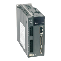
SV-DA200 series AC servo drive Control mode applications
-63-
4.4.6 Analog input signals and functions
Precision of AD1 is 16-bit and precision
of AD2 and AD3 is 12-bit.
If standard model (there is “-S” in the
drive nameplate) is used as the speed
control, AD1 channel is invalid, please
take AD3 as the speed command input
terminal and modify P3.70 to “speed
command”.
External analog input terminals. The
input impedance is 10kΩ. The input
voltage range is -10V–+10V. A voltage
exceeding ±11V may damage the drive.
The range and offset setting and
function definition can be set.
4.4.7 Encoder output signals and functions
Output the frequency divided encoder signal, comply with
the standard of TIA/EIA-422-B.
The output phase A pulse and phase B pulse is still
quadrature. When it rotates forward, phase B leads phase A
by 90º. When it rotates in reverse, phase A leads phase B
by 90º.
Frequency division and frequency multiplication with any
integer and decimal fraction is allowable.
The output signals have no isolation.
Output the open-collector signal of phase A, without
isolation
Output the open-collector signal of phase B, without
isolation
Output the open-collector signal of phase Z, without
isolation
4.4.8 Analog output signals and functions
Its output function definition can be set, and the range and offset
settings can be set.
Its output function definition can be set, and the range and offset
settings can be set.

 Loading...