SV-DA200 series AC servo drive Function codes
-138-
6.4.2 Analog input / output adjustment
This parameter can be used to adjust the analog input 1 to improve the effective accuracy of the
analog input.
Due to zero drift of the AI devices or induced voltage of ambient environment and other reasons,
the actual corresponding quantity of AI may deviate from the expected value, and such deviation
can be eliminated by setting the offset of AI.
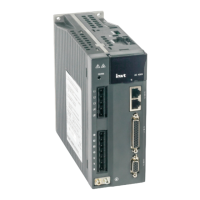
The meaning of the analog offset voltage is shown in below figure:
-10V
10V
Actual voltage (V)
Sampling voltage (V)
After setting
P3.20
P3.23
Before setting
For example, after analog input 1 command terminal of the drive is connected with analog
reference signal, then even if the analog reference signal is 0, the voltage value of analog input 1
(R1.05) displayed by the panel will be 0.02V, P3.20 should be set to 0.02 at this time. The drive
will automatically subtract 0.02V from the analog input value received. If the analog input 2
voltage displayed by the panel is -0.02V, then parameter P3.20 should be set to -0.02. The drive
will automatically add 0.02V to the analog input value received and the value displayed by the
panel will change at the same time.
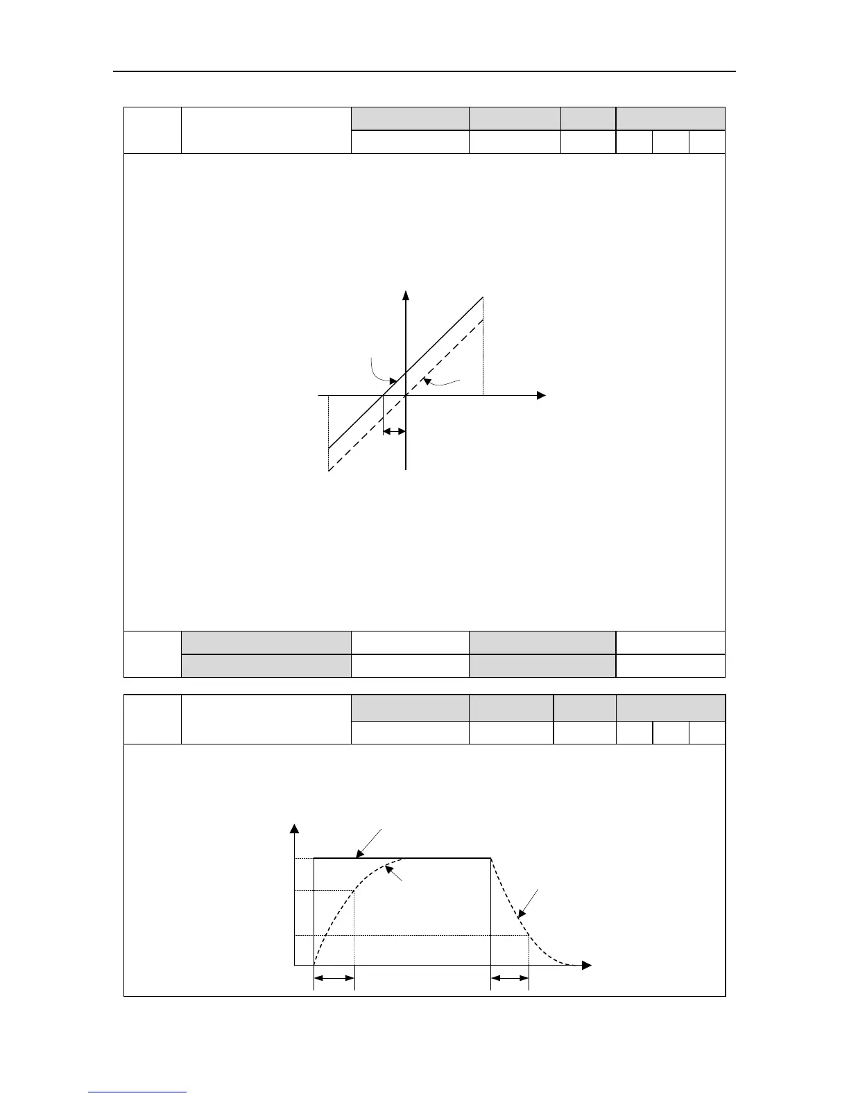
This parameter is used to set the time constant of the first order low-pass filter corresponds to
analog input 1. Setting this parameter can smooth the command changing when the analog input
changes violently. Please refer to the figure below:
Command before filtering
AD1
Time
Command after filtering
Command after filtering
P3.21P3.21
Vc
0.632Vc
0.368Vc
 Loading...
