SV-DA200 series AC servo drive Control mode applications
-70-
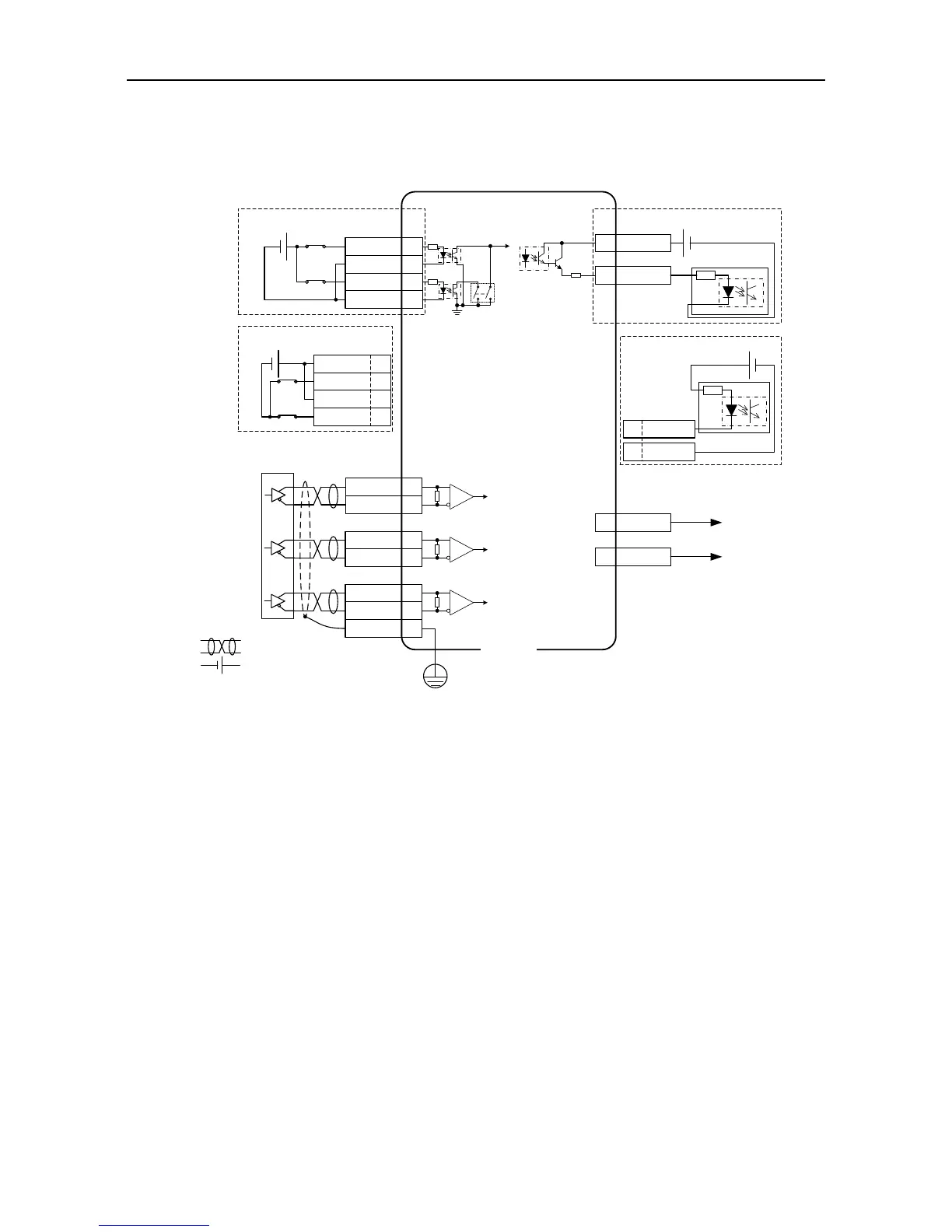
4.6 CN5 wiring diagram
4.6.1 CN5 wiring diagram of small power range (100W–5.5kW)
2
nd
encoder and STO
Differential command pulse input
(Max 4Mpps)
EXA+ 3
EXA- 4
EXB+ 10
EXB- 9
EXZ+ 14
- +
EXZ- 13
FG
HWBB1+ 1
HWBB1- 7
HWBB2+ 2
HWBB2- 8
WheN S1 set To ON, sAfetY
input termiNal signaL is
inValId, anD sErvo can Work
Normally; when S1 is set to
OFF, the servo can work
normally only if the safety
input terminal signal is valid
at the same time.
- +
HWBB1+ 1
HWBB1- 7
HWBB2+ 2
HWBB2- 8
S1STO switch
5 EX5V
12 EX0V
EX0V
EX5V
Safety terminal signal is active-low
Safety terminal signal is active-high
CN5
6 EDM+
11 EDM-
+ -
Safety output signal is active-high
Safety output signal is active-low
6 EDM+
11 EDM-
+ -
Note: 1. ( ) is shielded twisted pair;
2. ( ) is power source, DC12~24V which
is prepared by the user.
 Loading...
