EasyManua.ls Logo

INVT SV-DA200 Series User Manual

INVT SV-DA200 Series
300 pages
To Next Page IconTo Next Page
To Previous Page IconTo Previous Page
Page #81 background imageLoading...
Page #81 background image
SV-DA200 series AC servo drive Running and operation
-77-
COM-. Then the servo enters into the locking state.
9. The motor shaft may rotate at a low speed if there is no upper command voltage. It is
necessary to adjust P3.20. Please refer to the detailed instruction of P3.20.
5.1.5 Running at the torque control mode
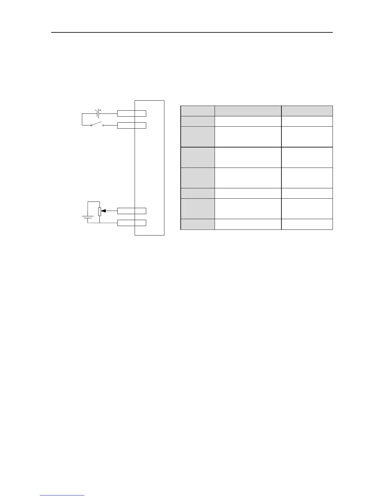
Simple connection:
SON 16
COM+ 2
DC
12~24V
AD2 20
GND 5
Servo drive
CN1
+
-
Torque
command for
upper analog
0~±10V
Steps:
1. Complete the connection between the drive and the servo motor.
2. Set P0.03 to “2”, the torque control mode.
3. It is necessary to disconnect the control power supply after saving the modified value of
P0.03. And it will be valid after repowering on.
4. Set P0.60 to “1”, external analog torque command mode.
5. Set P0.61 to the required value. Please refer to the instruction of P0.61.
6. Set P3.26 to “4”, analog input 1 is torque command;
7. Set P0.62 to the required value. Please refer to the instruction of P0.62.
8. Connect the corresponding terminals of CN1.
9. Connect the CN1 to the drive and power on. Control the connection between SON and
COM-. Then the servo enters into the locking state.
10. The motor shaft may rotate at a low speed if there is no upper command voltage. It is
necessary to adjust P3.23. Please refer to the detailed instruction of P3.23.
11. In the torque mode, please adjust the speed limit and set P0.46 to the required value. Please
refer to the detailed instruction of P0.46.
5.1.6 Parameter setting before running the servo
Parameter setting must be conducted before running the servo. Relevant parameters can be set via
the panel, PC software or communication to meet the function and performance requirements of the
site application. See chapter 6 for the detailed description of all parameters of the servo drive. Some
Parameter
Function
Setting value
P0.03
1
Mode selection
2
P0.60
Torque command
selection
1
P3.27
Function of analog
input 2
4
P0.61
Torque command
direction selection
Set according to
requirement
P0.62
Analog input 2 gain
10
P3.23
Analog input 2 offset
Set according to
requirement
P0.46
Speed limit 1
100

Table of Contents

Other manuals for INVT SV-DA200 Series

Questions and Answers:

INVT SV-DA200 Series Specifications

General IconGeneral
BrandINVT
ModelSV-DA200 Series
CategoryServo Drives
LanguageEnglish

Summary

Preface

Safety Precautions

Safety Symbols and General Precautions

Details safety symbols, recycling information, and general precautions for safe operation.

1 Product Overview

1.1 Servo Drive

Describes the SV-DA200 series AC servo drive, its functions, and interface details.

2 Installation Instruction

2.1 Drive Dimension

Details the physical dimensions and diagrams for various drive sizes (A/B/C, D, F/F2, G, H).

2.2 Drive Installation

Covers the methods for installing the servo drive, including base and bracket installations.

2.2.2 Installation Space and Direction

Specifies the required installation space and orientation for optimal ventilation and performance.

2.3 Motor Dimension

Provides outline and installation dimensions for various servo motor bases (40, 60, 80, 110, 130, 180, 200, 263 mm).

3 Wiring Instruction

5 Running and Operation

5.1 Running

Provides instructions for powering on the system, checking connections, and performing initial operations.

5.1.1 First Powering On

Details the steps and checks required before the initial power-on of the servo drive.

5.1.4 Running at the Speed Control Mode

Guides on configuring and running the servo drive in speed control mode using simple connections.

5.1.5 Running at the Torque Control Mode

Provides instructions for operating the servo drive in torque control mode with simple connections.

5.1.6 Parameter Setting Before Running the Servo

Outlines the necessary parameter settings before the servo drive can be operated.

5.1.7 Servo Enabling

Explains how to enable the servo via terminal or parameter settings and its operational effects.

5.1.8 Servo Stop/Stop Running

Describes conditions and methods for stopping the servo motor, including coasting and normal stopping.

6 Function Codes

6.1 Basic Control (P0 Group Parameters)

Covers basic control parameters, including motor model, encoder type, and control mode selection.

6.1.1 Basic Setting

Explains parameters like motor model, encoder type, and forward rotation settings.

6.1.2 Position Control

Details parameters related to position control, including command selection and pulse input.

6.1.3 Speed and Torque Control

Covers parameters for speed command selection and torque limit settings.

6.2 Autotuning Control Parameters (P1)

6.2.1 Inertia Identification (Automatic Gain)

Explains how to perform online and offline inertia identification for automatic gain adjustment.

6.2.2 Self-Adaptive Vibration Control

Covers parameters for self-adaptive vibration control, including resonance detection and notch filters.

6.3 Motor Control Parameters (P2)

6.3.1 Gain Setting

Explains parameters for setting speed, position, and torque gains, and their impact on system performance.

6.4 I/O Management Parameters (P3)

6.6 Program JOG, Homing and PTP Control (P5)

6.6.1 Program JOG

Details parameters and operation modes for the JOG function, including movement amount and speed settings.

6.6.2 Homing

Covers parameters and modes for homing operations, including automatic homing and step settings.

6.6.3 PTP (Point-to-Point ) Control

Explains parameters for Point-to-Point (PTP) control, including control words and position settings.

6.9 State Monitoring

6.9.3 Fault Record Parameter (R3)

Explains parameters related to fault records, including codes, power-on time, and motor speed during faults.

7 Commissioning

7.1 Operation Instruction of Inertia Identification

Details the procedures for both online and offline inertia identification.

7.2 General Method for Parameters Adjusting

Explains general methods for adjusting servo system parameters, including rigidity and loop gains.

7.3 Suppression of Mechanical Resonance

Covers techniques for suppressing mechanical resonance using notch filters and their parameters.

7.4 Gain Switching Function

Explains how gain switching operations are performed and their benefits in different states.

8 Communication

8.2 RS485 Communication Protocol

Explains the RS485 communication protocol, including frame structure, command codes, and error checking.

8.3 CANopen Communication Protocol

Details the CANopen protocol, including hardware configuration, software configuration, and functions.

8.4 PROFIBUS-DP Communication Protocol

Covers the PROFIBUS-DP protocol, its introduction, hardware configuration, and software configuration.

9 Faults and Solutions

9.1 Meanings of the Fault Alarm Code and Countermeasures

Details fault codes, their associated causes, and recommended countermeasures for resolution.

9.2 CANopen Communication Fault Code and Countermeasures

Lists CANopen communication fault codes and their respective countermeasures.

9.3 PROFIBUS-DP Communication Fault Code and Countermeasures

Provides fault codes and countermeasures for PROFIBUS-DP communication issues.

9.4 EtherCAT Communication Fault Code and Countermeasures

Details EtherCAT communication fault codes and their corresponding solutions.

10 Appendix

10.4 Fault Code

Provides a summary of fault codes, their names, and whether they are recordable, clearable, or disableable.

Related product manuals