SV-DA200 series AC servo drive Running and operation
-81-
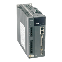
5.1.9.2 Sequence diagram of power loss during running
Main power
Control power
PWM output
Electromagnetic
brake release signal
output (BRK)
Servo ready output
(RDY)
Microcontroller state
Note 1: If the voltage of the control circuit is less than 170V/330V(220V series/400V series), the
undervoltage fault will occur and the output level of the servo fault (ALM) will increase;
Note 2: If the drive temperature is less than 45 , the fan stops, if the drive temperature is higher than
45 , the fan will stop after the micro processor stops;
Note 3: The output delay of electromagnetic brake release signal is set by P3.57; if the speed slows
down to the setting value of P3.58 (30r/min by default) during the time set by P3.57, BRK signal will
become invalid;
Note 4: The actual level corresponding to input/output valid state can be set by P3.00~P3.15
Note 1
Control circuit power disconnection
Main circuit power loss
Program stops running
Servo has output
Motor brakeMotor brake-release
Servo has no output
Fan signal Fan stops runningFan running
Note 2
Note 3
Valid Invalid
Program running
Note 4
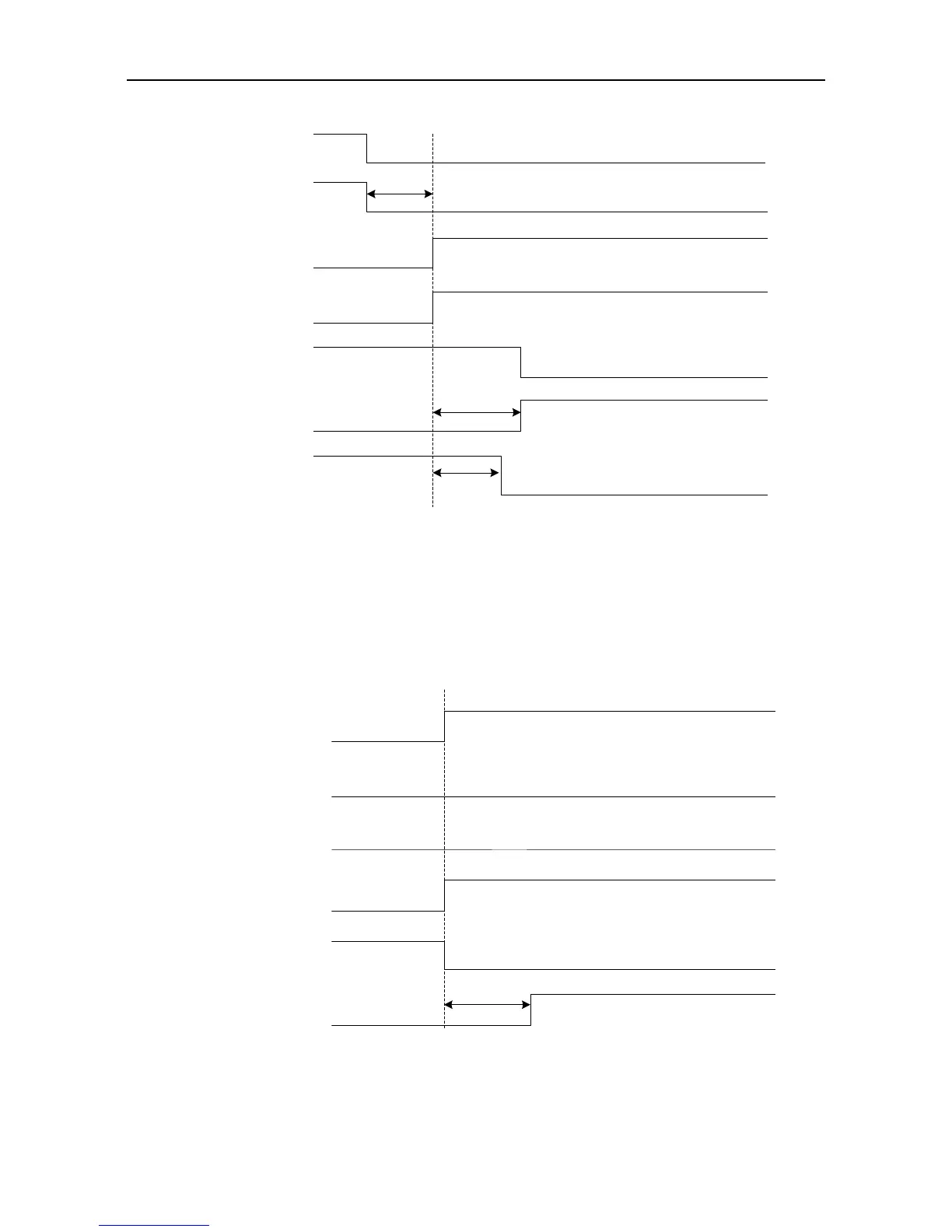
Dynamic brake state
PWM output
Electromagnetic
brake release signal
output (BRK)
Servo ready output
(RDY)
Servo fault output
(ALM)
Servo enabling (SON)
Note 1: The startup of dynamic brake can be set by P4.30;
Note 2: The servo locking time after braking can be set by P3.56;
Note 3: The actual electric level corresponding to I/O valid state can be set by P3.00~P3.15.
No fault alarm
Servo has output
Motor brakeMotor brake-release
Servo has no output
Dynamic brake switches onNote 1
Note 2
Normal
Dynamic brake
switches off
Enable Disable
Note 3
 Loading...
