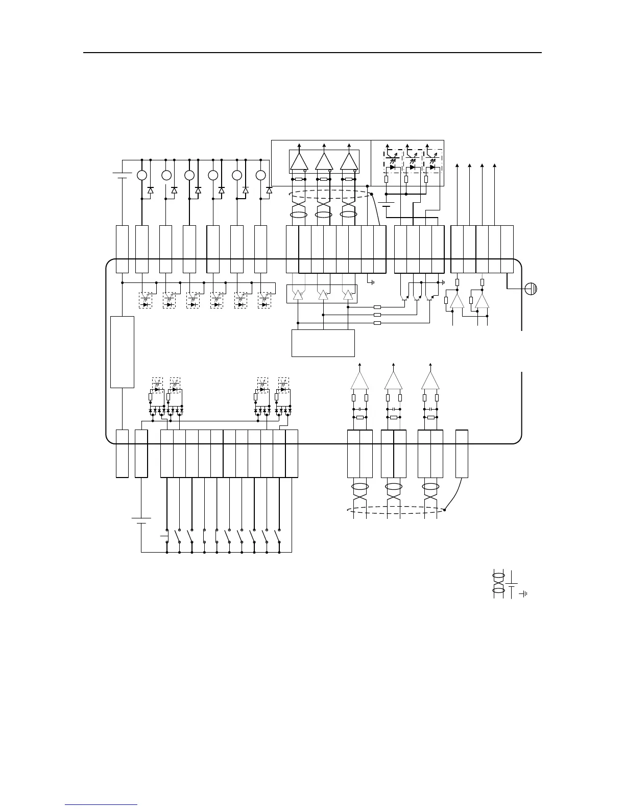
Speed control mode
Load capacity of
each output
terminal is
DC30V, 50mA
EMG 39
SON 16
ZRS 37
POT 3
NOT 4
CLA 10
SPD1 34
SPD2 17
S/SIGN 18
PLC 22
Gain switching
Speed command
symbol
Internal speed
command 2
Internal speed
command 1
Alarm clearing
Negative direction
drive disabled
Emergency stop
Servo enabling
Zero speed clamp
Positive direction
drive disabled
COM- 12
COM+ 2
24V 40
Internal DC24V power
Note: Capacity 100mA
12 COM-
15 ALM
14 RDY
29 ZSO
11 COIN
13 LM
9 BRK
FG
21 AO1
5 GND
25 AO2
6 GND
FG
Torque monitoring output
Speed monitoring output
Fault
Servo ready
Speed zero
Speed matching
Torque limiting
Brake release
Speed command input
(-10V~+10V)
AD1 1
GND 5
When non-standard model is selected, AD1
channel is invalid. Please use AD3 channel
and confirm P3.70 is speed command.
AD2 20
GND 19
AD3 7
GND 8
Analog torque limit of positive direction
(0V~+10V)
Analog torque limit of negative direction
(-10V~0V)
Note: User-supplied power
DC12~24V
- +
Note: User-supplied power
VccDC30V
- +
Frequency
divider
36 OCA
External
controller
44 OA+
43 OA-
41 OB+
42 OB-
FG
26 OCZ
30 OCB
AM26LS32
or equivalent chip
V
cc
DC30V;
OCA/B/Z output
current50mA
28 OZ+
27 OZ-
High speed optical
coupler
35 GND
GND
- +
Vcc
5 GND
CN1
Output voltage range:
DC -10V~+10V;
Max output current:
3mA.
DI input
common port
DO output common
ground
Ref
Note: 1. ( ) is shielded twisted pair;
2. ( ) is power which is provided by the user;
3. ( ) is GND, pin numbers are 5/6/8/19/35.
DO output
common ground
 Loading...
