SV-DA200 series AC servo drive Control mode applications
-67-
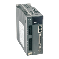
4.5.3 Wiring of the analog input circuit
0
0
0
1 AD1
5 GND
20 AD2
A
D
C
FG
Please connect shielded
cable according to the
device requirement
Twisted
pair
19 GND
0
0
0
Drive side
Control module
side
There are three analog input circuits, AD1, AD2 and AD3, precision of AD1 is 16-bit (optional for
standard models), precision of AD2 and AD3 is 12-bit (standard). The input impedance is 10kΩ.
The input voltage range is -10V–+10V. If the voltage is higher than ±11V, the circuits may be
damaged.
If the non-standard model is used as the speed control, AD1 channel is invalid, please take AD3
as the speed command input terminal and modify P3.70 to “speed command”.
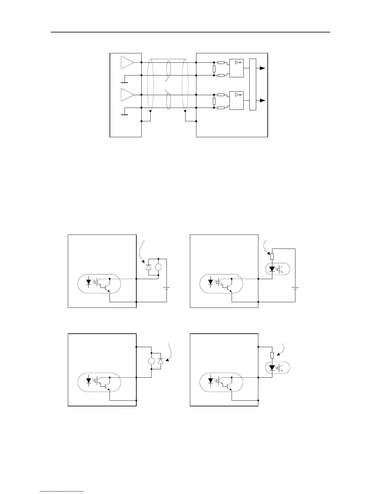
4.5.4 Wiring of digital output circuit
Connection diagram when the power supply is provided by user:
Users must install this
freewheeling diode when
connecting to inductive load
Max load capacity of each
output terminal: 30V, 50mA.
DC
12~24V
+
-
Drive side
DO1 14
COM- 12
Max load capacity of each
output terminal: 30V, 50mA.
+
-
RY
DC
12~24V
connect to relay coil
connect to optical coupler
DO1 14
COM- 12
Users must connect to current
limit resistor when connecting
to optical coupler
Drive side
Connection method when the local power supply is used:
Users must install this
freewheeling diode when
connecting to conductive load
Max load capacity of each
output terminal:
30V, 50mA.
Drive side
DO1 14
COM- 12
Max load capacity of each
output terminal:
30V, 50mA.
RY
connect to relay coil
connect to optical coupler
DO1 14
COM- 12
Users must connect to current
limit resistor when connecting
to optical coupler
Drive side
24V 40 24V 40
There are 6 digital output circuits in total and all of them adopt the open-collector output as
shown in the figure. They can be used to drive the relay coil or optical coupled load. The loading
capacity is shown in the figure.
 Loading...
