EasyManua.ls Logo

Omron NX701-1 User Manual

Omron NX701-1
448 pages
To Next Page IconTo Next Page
To Previous Page IconTo Previous Page
Page #159 background imageLoading...
Page #159 background image
6-7
6 Motion Control Programming
NJ/NX-series CPU Unit Motion Control Users Manual (W507)
6-3 State Transitions
6
6-3-2 Axis States
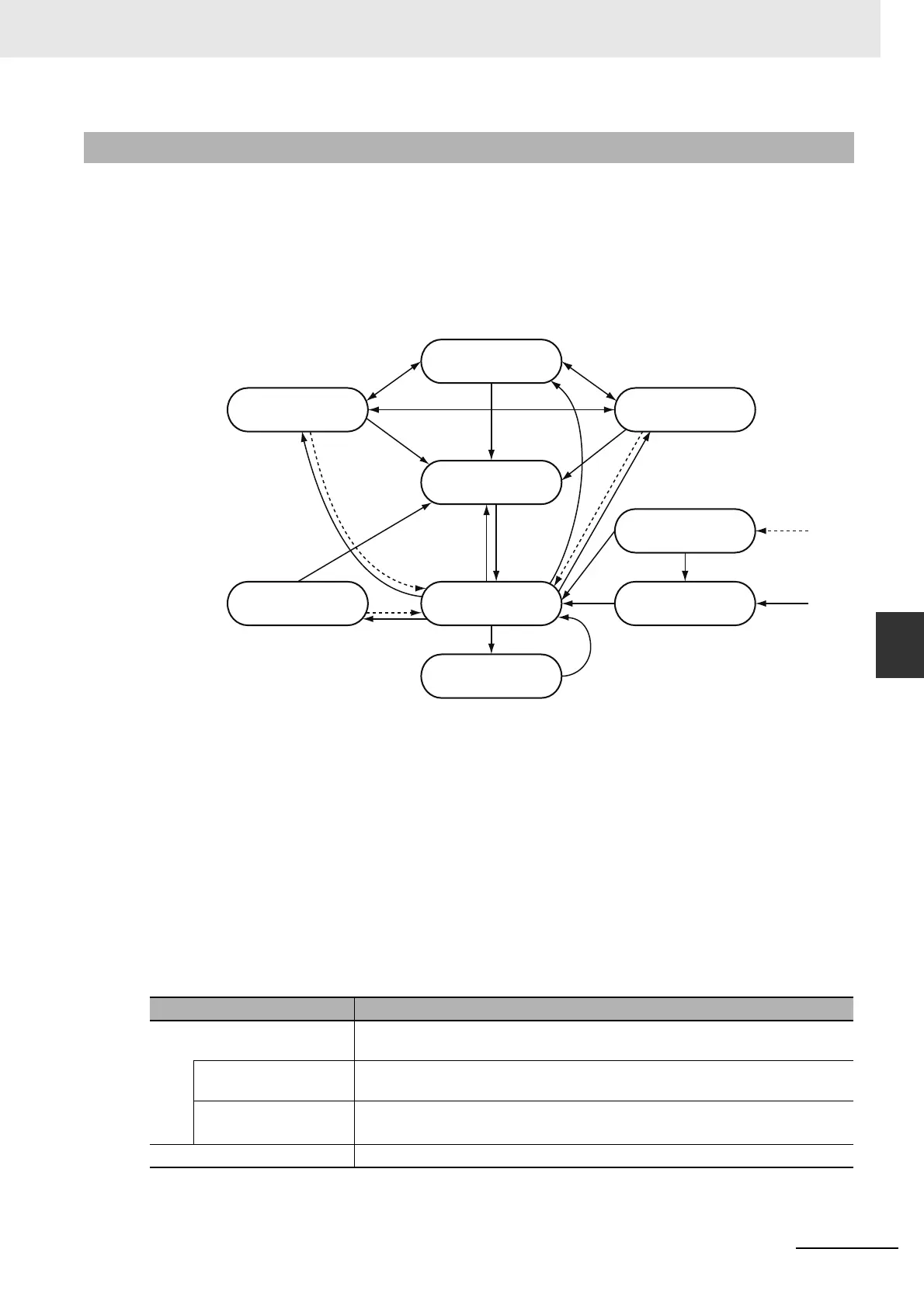
The operation of an axis when motion control instructions are executed for it is shown in the following
figure. Motion control instructions are executed in sequence and axes enter one of the states listed in
the following table.
*1 Transition into this state occurs when there is an axis error in any state except for Coordinated Motion state.
*2 Transition into this state occurs when there are no axis errors and the Status output to the MC_Power instruc-
tion is FALSE. (The Servo is OFF.)
*3 Transition into this state occurs if an error is reset with the MC_Reset or ResetMCError instruction when the
Servo is OFF.
*4 Transition into this state occurs if an error is reset with the MC_Reset or ResetMCError instruction when the
Servo is ON.
*5 Transition into this state occurs when the Enable input to the MC_Power instruction changes to TRUE and the
Status (Servo ON) output from the MC_Power instruction changes to TRUE. (The Servo is ON.)
*6 Transition into this state occurs when the Done output from the MC_Stop instruction is TRUE and the Execute
input to the MC_Stop instruction changes to FALSE.
*7 Transition into the Deceleration Stopping state occurs when the MC_ResetFollowingError instruction is exe-
cuted.
*8 The Continuous Motion state exists from when velocity control is set for the MoveMode input variable of the
MC_MoveFeed instruction until a trigger input is detected.
6-3-2 Axis States
State name Definition
Servo OFF In this state, the Servo is OFF for the axis. When this state is moved to, the
buffered status for multi-execution of instructions is cleared.
Axis Disabled In this state, the Servo is OFF for the axis, the axis is stopped, and execution
preparations are completed.
Error Deceleration
Stopping
*1
In this state, the Servo is OFF for the axis, the axis is stopped, and an axis error
has occurred.
Servo ON In this state, the Servo is ON for the axis.
*6
*3
*1
*2
*5
MC_Stop
*4
MC_Home
MC_HomeWithParameter
MC_Move
MC_MoveAbsolute
MC_MoveRelative
MC_MoveFeed
MC_MoveZeroPosition
MC_GearOut
MC_CamOut
MC_SyncMoveVelocity
MC_MoveVelocity
MC_TorqueControl
MC_MoveJog
MC_ImmediateStop
*7: MC_ResetFollowingError
*7
*8
Axis Disabled
Disabled
Error Deceleration Stopping
ErrorStop
Continuous Motion
Continuous
Coordinated Motion
Coordinated
Standstill
Standstill
Deceleration Stopping
Stopping
Homing
Homing
Discrete Motion
Discrete
MC_MoveLink (slave axis)
MC_CombineAxes (slave axis)
MC_CamIn (slave axis)
MC_GearInPos (slave axis)
MC_GearIn (slave axis)
Synchronized Motion
Synchronized

Table of Contents

Question and Answer IconNeed help?

Do you have a question about the Omron NX701-1 and is the answer not in the manual?

Omron NX701-1 Specifications

General IconGeneral
Ethernet Ports1
USB Ports1
Power Supply24 VDC
I/O PointsUp to 256
Ethernet Port1
USB Port1
SD Memory Card SlotYes
Programming LanguageLadder Diagram, Structured Text, Function Block Diagram
Operating Temperature0 to 55°C

Summary

Introduction

Intended Audience

Information about the target readers of this manual.

Applicable Products

Lists the specific CPU Units covered by this manual.

Relevant Manuals

Manual Structure

Special Information

Precaution on Terminology

Sections in this Manual

Terms and Conditions Agreement

Safety Precautions

Definition of Precautionary Information

Explains the classification of precautionary information within the manual.

Precautions for Safe Use

Precautions for Correct Use

Regulations and Standards

Versions

Checking Versions

Explains how to check unit versions using ID information or Sysmac Studio.

Related Manuals

Revision History

1 Introduction to the Motion Control Function Module

1-1 Features

Describes the capabilities of the Motion Control Function Module.

1-2 System Configuration

Outlines the system components and network configuration for motion control.

1-3 Basic Flow of Operation

Provides a step-by{0}step procedure for performing motion control.

1-4 Specifications

Details the performance and general specifications of the MC Function Module.

2 Motion Control Configuration and Principles

2-1 Internal Configuration of the CPU Unit

Overview of the CPU Unit's software configuration and function modules.

2-2 Motion Control Configuration

Details the configuration of motion control on EtherCAT networks and CPU Units.

2-3 Motion Control Principles

Explains CPU Unit tasks and their relation to motion control execution.

2-4 EtherCAT Communications and Motion Control

Describes EtherCAT communications and their relation to motion control.

3 Configuring Axes and Axes Groups

3-1 Axes

Describes the different types of axes used in motion control systems.

3-2 Axis Setting Procedure

Provides step-by-step instructions for setting up axes in Sysmac Studio.

3-3 Axes Groups

Explains how to group axes for complex operations like linear or circular interpolation.

3-4 Setting Procedures for Axes Groups

Details the procedures for setting up axes groups in Sysmac Studio.

4 Checking Wiring from the Sysmac Studio

4-1 Functions of the Sysmac Studio

Explains how to use the MC Test Run function for wiring checks without programming.

4-2 Monitoring Sensor Signals

Describes how to use the input signal display to check sensor wiring.

4-3 Checking Motor Operation

Details how to check motor operation using functions like Servo ON and Jogging.

5 Motion Control Parameters

5-1 Introduction

Explains axis and axes group parameters for motion control operations.

5-2 Axis Parameters

Details various parameters for configuring axis operations.

5-3 Axes Group Parameters

Explains parameters for setting up axes group operations.

6 Motion Control Programming

6-1 Introduction

Explains programming motion control with EtherCAT slave devices.

6-2 Motion Control Instructions

Provides an overview of motion control instructions based on PLCopen® and MC Function Module specific ones.

6-3 State Transitions

Describes the states of axes and axes groups and their transitions.

6-4 Execution and Status of Motion Control Instructions

Details the rules for executing instructions and their status monitoring.

6-5 Positions

Explains the different types of positions used in motion control programming.

6-6 System-defined Variables for Motion Control

Describes system-defined variables for status and parameter information.

6-7 Cam Tables and Cam Data Variables

Explains the creation and handling of cam tables and cam data variables.

6-8 Programming Motion Controls

Provides procedures for creating programs in Sysmac Studio.

6-9 Creating Cam Tables

Explains how to use the Cam Editor in Sysmac Studio to create cam tables.

7 Manual Operation

7-1 Outline

Describes manual operations using the MC Function Module and OMRON Servo Drives.

7-2 Turning ON the Servo

Details how to turn the Servo ON/OFF using the MC_Power instruction.

7-3 Jogging

Explains how to perform axis jogging using the MC_MoveJog instruction.

8 Homing

8-1 Outline

Describes homing operations when combined with OMRON G5-series Servo Drives.

8-2 Homing Procedure

Provides the steps for setting homing parameters and performing the homing operation.

8-3 Homing Operation

Explains how to select the home definition method based on system configuration and purpose.

8-4 Homing with an Absolute Encoder

Describes how to use absolute encoders for homing and retaining position data.

8-5 High-speed Homing

Explains the function for quick positioning to home using MC_MoveZeroPosition.

9 Motion Control Functions

9-1 Single-axis Position Control

Describes positioning operations for single axes connected to OMRON Servo Drives.

9-2 Single-axis Synchronized Control

Explains synchronized control for single axes using gear or cam operations.

9-3 Single-axis Velocity Control

Details the operation of velocity control for single axes.

9-4 Single-axis Torque Control

Explains how torque control continuously applies a specified amount of torque.

9-5 Common Functions for Single-axis Control

Describes common functions like positions, velocity, and acceleration for single-axis control.

9-6 Multi-axes Coordinated Control

Explains how to set up axes groups for interpolation control of multiple axes.

9-7 Common Functions for Multi-axes Coordinated Control

Details common functions for multi-axes coordinated control, like velocity and acceleration.

9-8 Other Functions

Describes additional functions of the MC Function Module.

10 Sample Programming

10-1 Overview of Sample Programming

Provides information applicable to all sample programming sections.

10-2 Basic Programming Samples

Offers programming samples for MC Function Module's basic functions.

11 Troubleshooting

11-1 Overview of Troubleshooting

Describes methods for checking errors and finding corrections.

Appendices

A-1 Connecting the 1S-series Servo Drive

Describes connections and settings for OMRON 1S-series Servo Drives.

A-2 Connecting the G5-series Servo Drive

Describes connections and settings for OMRON G5-series Servo Drives.

A-3 Connecting to Encoder Input Terminals

Details connections and settings for OMRON GX-series Encoder Input Terminals.

A-4 Connecting to NX Units

Provides information on connecting to NX-series Position Interface Units.

A-5 PDS State Transition

Explains PDS state transitions defined in CiA402 drive profile.

A-6 Terminology

Provides definitions of terms related to motion control.

A-7 Version Information

Details functions added or changed for different CPU Unit and Sysmac Studio versions.

Related product manuals