10 Sample Programming
10-40
NJ/NX-series CPU Unit Motion Control User’s Manual (W507)
This sample performs interrupt feeding when an interrupt occurs during velocity control. One of the fol-
lowing is specified for the Direction variable when velocity control is performed in Rotary Mode.
• _mcPositiveDirection
• _mcNegativeDirection
• _mcCurrentDirection
This sample uses _mcCurrentDirection. A positive value is specified for the FeedDistance input vari-
able to perform feeding in the same direction as the motion before the interrupt input. A negative value
is specified for the FeedDistance input variable to perform feeding in the opposite direction as the
motion before the interrupt input. For example, if a positive value is specified for the FeedDistance input
variable when the motion was in the negative direction before the interrupt input, feeding is performed
in the negative direction. If a negative value is specified for the FeedDistance input variable, feeding is
performed in the positive direction.
10-2-11 Interrupt Feeding
Axis Parameter Settings
Parameter name Setting Description
Count Mode Rotary Mode Rotary Mode is set as the count mode for the position.
Modulo Maximum Position
Setting Value
360 The Modulo Maximum Position is set to 360.
Modulo Minimum Position
Setting Value
0 The Modulo Minimum Position is set to 0.
Homing Method Zero position preset A zero position preset is performed to define home.
Main Variables Used in the Programming Samples
Variable name Data type Default Comment
MC_Axis000 _sAXIS_REF --- This is the Axis Variable for axis 0.
MC_Axis000.MFaultLvl.Active BOOL FALSE TRUE when there is a minor fault level error
for axis 0.
MC_Axis000.Details.Homed BOOL FALSE TRUE when home is defined for axis 0.
StartPg BOOL FALSE When StartPg is TRUE, the Servo is turned
ON if EtherCAT process data communica-
tions are active and normal.
Pwr_Status BOOL FALSE This variable is assigned to the Status output
variable from the PWR instance of the
MC_Power instruction. It is TRUE when the
Servo is ON.
TrigRef _sTRIGGER_REF --- This parameter specifies the trigger input
condition to use for the interrupt input. Latch
1 of the Servo Drive is used in this sample.
Hm_Ex BOOL FALSE This variable is used to execute the
MC_Home instruction. It is used in ST pro-
gramming.
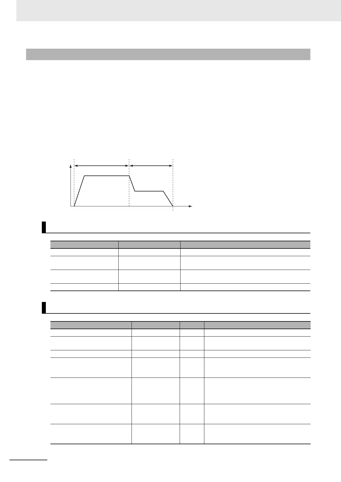
Time
Velocity
Velocity control Interrupt feeding