10-5
10 Sample Programming
NJ/NX-series CPU Unit Motion Control User’s Manual (W507)
10-2 Basic Programming
Samples
10
10-2-2 Interlocking Axis Operation with Master Control Instructions
You can place the MC_Power (Power Servo) instruction between the MC (Master Control Start) and
MCR (Master Control End) instructions in ladder diagrams to interlock axis operation. When Mc_On is
FALSE in this sample, the MC_Power (Power Servo) instruction between the MC and MCR instructions
is disabled to turn OFF the Servo. The CommandAborted output variable from the current motion con-
trol instruction changes to TRUE at the same time, and axis motion stops.
You cannot use the MC instruction in ST. Therefore, a sample is provided only for a ladder diagram.
10-2-2 Interlocking Axis Operation with Master Control Instructions
Main Variables Used in the Programming Samples
Variable name Data type Default Comment
MC_Axis000 _sAXIS_REF --- This is the Axis Variable for axis 0.
MC_Axis000.MFaultLvl.Active BOOL FALSE TRUE when there is a minor fault level error for
axis 0.
Mc_On BOOL FALSE This variable enables and disables the MC
instruction. Control programming is not given in
this sample. In actual programming, program
controls for the required device operation.
StartPg BOOL FALSE When StartPg is TRUE, the Servo is turned ON
if EtherCAT process data communications are
active and normal.
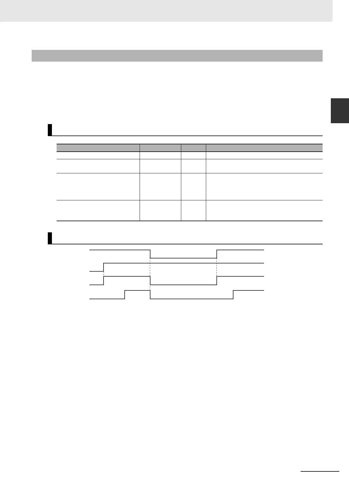
Timing Chart
Pwr_Bsy
Mc_On
StartPg
Pwr_Status