10-19
10 Sample Programming
NJ/NX-series CPU Unit Motion Control User’s Manual (W507)
10-2 Basic Programming
Samples
10
10-2-7 Stopping Axes during Single-axis Operation
In this sample, the MC_Stop instruction is executed to decelerate to a stop if an external button turns
ON during execution of the MC_MoveAbsolute (Absolute Positioning) instruction. If there is a minor
fault level error, the CommandAborted output variable from the MC_Stop instruction changes to TRUE.
In that case, the MC_ImmediateStop instruction is executed to stop immediately. If for any reason the
Error output variable from the MC_Stop instruction changes to TRUE, the MC_ImmediateStop instruc-
tion is executed to stop immediately. If the MC_ImmediateStop instruction is executed, the axis status is
Error Deceleration Stopping.
Samples are provided for both ladder diagram and ST programming.
10-2-7 Stopping Axes during Single-axis Operation
Main Variables Used in the Programming Samples
Variable name Data type Default Comment
MC_Axis000 _sAXIS_REF --- This is the Axis Variable for axis 0.
MC_Axis000.MFaultLvl.Active BOOL FALSE TRUE when there is a minor fault level error for
axis 0.
MC_Axis000.Details.Homed BOOL FALSE TRUE when home is defined for axis 0.
Pwr_Status BOOL FALSE This variable is assigned to the Status output
variable from the PWR instance of the
MC_Power instruction. It is TRUE when the
Servo is ON.
Stp_Ca BOOL FALSE This variable is assigned to the Command-
Aborted output variable from the STP instance
of the MC_Stop instruction.
Stp_Err BOOL FALSE This variable is assigned to the Error output
variable from the STP instance of the MC_Stop
instruction.
StartPg BOOL FALSE When StartPg is TRUE, the Servo is turned ON
if EtherCAT process data communications are
active and normal.
StopOn BOOL FALSE This variable gives the status of the external
button that is used to stop. The MC_Stop
instruction is executed to stop the axis if this
variable is TRUE.
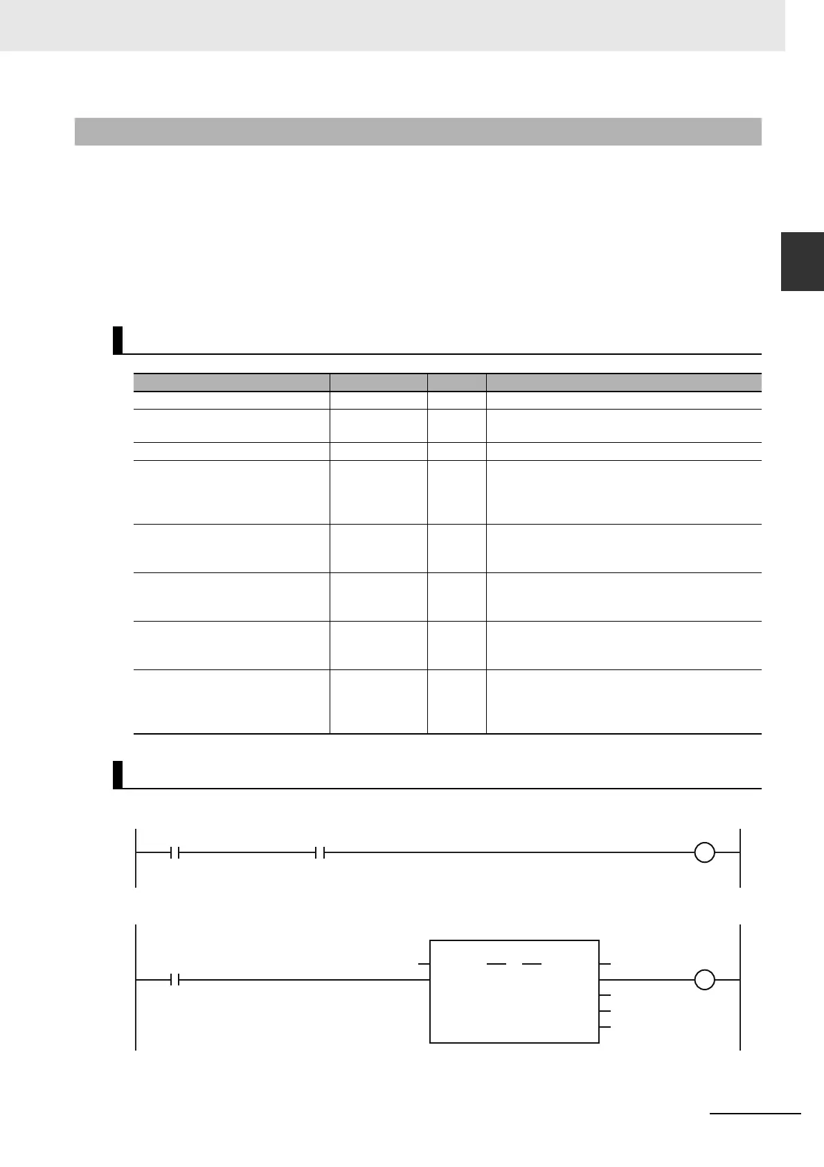
Ladder Diagram
StartPg
Lock0
MC_Axis000.DrvStatus.Ready
PWR
Error
Axis Axis
Enable Status
Busy
MC_Power
ErrorID
Lock0
MC_Axis000
Pwr_Status
Pwr_Bsy
Pwr_Err
Pwr_ErrID
Check if the Servo Drive for axis 0 is ready when StartPg is TRUE.
If the Servo Drive for axis 0 is ready, turn ON the Servo for axis 0.