9-13
9 Motion Control Functions
NJ/NX-series CPU Unit Motion Control User’s Manual (W507)
9-2 Single-axis Synchronized Control
9
9-2-1 Overview of Synchronized Control
9-2 Single-axis Synchronized Control
This section describes the operation of synchronized control for single axes.
Synchronous control synchronizes the position of a slave axis with the position of a master axis. The
command position or actual position of any axis can be specified for the master axis. If the command
velocity for the slave axis exceeds the maximum velocity that is set in the axis parameters, the com-
mand is performed at the maximum velocity of the axis. If this occurs, any insufficient travel distance is
distributed and output in the following periods.
Precautions for Correct UsePrecautions for Correct Use
• You cannot specify an encoder axis, virtual encoder axis or single-axis position control axis for
the slave axis.
• When you use an NX701 CPU Unit and operate in the multi-motion, assign the master axis
and slave axis to the same task.
If you specify the master axis in a different task from the slave axis by executing the synchro-
nized control instructions such as the MC_GearIn (Start Gear Operation) instruction or the
MC_Camin (Start Cam Operation) instruction, an Illegal Master Axis Specification (event code:
54620000 hex) occurs.
Refer to 9-2-10 Achieving Synchronized Control in Multi-motion if you desire to specify the
master axis in a different task from the slave axis.
This function specifies the gear ratio between the master axis and the slave axis and starts operation.
Start gear operation with the MC_GearIn (Start Gear Operation) instruction. End synchronization with
the MC_GearOut (End Gear Operation) instruction or the MC_Stop instruction.
You can set the gear ratio numerator, gear ratio denominator, position type, acceleration rate, and
deceleration rate for the slave axis to operate. For the master axis, you can specify the command posi-
tion, actual position, or most recent command position.
After operation starts, the slave axis uses the velocity of the master axis times the gear ratio for its tar-
get velocity, and accelerates/decelerates accordingly. The catching phase exists until the target velocity
is reached. The InGear phase exists after that. If the gear ratio is positive, the slave axis and master
axis move in the same direction. If the gear ratio is negative, the slave axis and master axis move in the
opposite directions.
9-2-1 Overview of Synchronized Control
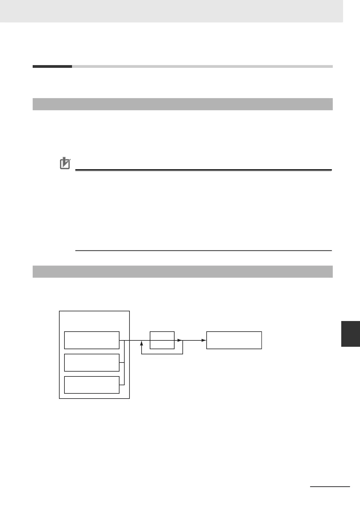
9-2-2 Gear Operation
Command position
Remainder
Denominator
Numerator
Gear Operation
Most recent command
position
Command position
Actual position
Specify with
Master_Reference.

 Loading...