104 Rockwell Automation Publication 750-TG100B-EN-P - June 2019
Chapter 6 Frame 7 Components
Control Pod Assembly
Replacement
Replace a control pod assembly with kit catalog number 20-750-MCPOD1-F7M
(regenerative drive or bus supply) or 20-750-MCPOD2-F7M (low harmonic
drive)
Remove the Control Pod Assembly
Follow these steps to remove the control pod assembly.
1. Review the Product Advisories on page 14
.
2. Remove power from the system. See Remove Power from the System on
page 15
.
3. Open the enclosure door.
4. Remove the control pod cover. See Remove the Control Pod Cover on
page 98
.
5. Disconnect the AC precharge circuit board fiber-optic cable from the
ACPC port on the fiber transceiver board.
6. If installed, disconnect the torque accuracy module fiber-optic cable from
the TAM port on the fiber transceiver board.
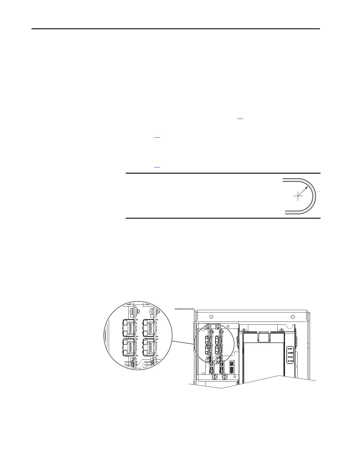
7. Disconnect the line side converter power module fiber-optic cables from
the L0 port on the fiber transceiver board.
8. Disconnect the motor side inverter power module fiber-optic cable from
the M0 port on the fiber transceiver board.
9. Route the fiber optic cables through the grommets in the bottom of the
control pod carefully, and coil the fiber-optic cable and secure in a
protected location. Follow the minimum bend radius requirement.
IMPORTANT
Minimum inside bend radius for fiber-optic cable is 50 mm
(2 in.). Any bends with a shorter inside radius can
permanently damage the fiber-optic cable. Signal
attenuation increases as inside bend radius is decreased.
 Loading...


