292 Rockwell Automation Publication 750-TG100B-EN-P - June 2019
Chapter 11 Start Up After Repairs
Frames 5 and 6
1. Measure the AC input and DC bus voltage at the following terminals to
verify that there is no voltage present:
• Use the R/L1, S/L2, and T/L3 terminals to measure L to L and L to
chassis GND (PE).
• Use the +DC and –DC terminals to measure +DC to –DC, +DC to
chassis GND (PE), and –DC to chassis GND (PE).
2. Perform phase to ground resistance tests to verify that there are no shorts
on the following locations:
• Use terminals R/L1, S/L2, and T/L3 to measure L to chassis GND
(PE).
• Use terminals +DC and –DC to measure +DC to chassis GND (PE),
and –DC to chassis GND (PE).
3. If the measured value of any resistance test is less than 1 k, troubleshoot
to find the short, correct the problem, and repeat step 2.
ATTENTION: To avoid an electric shock hazard, verify that there is no AC input
and DC bus voltage by taking these measurements:
• Verify that there is no AC input voltage present on the R/L1, S/L2, and
T/L3 terminals.
• Verify that there is no DC bus voltage present by using the +DC to –DC
terminals and measuring +DC to –DC, +DC to GND, and –DC to GND.
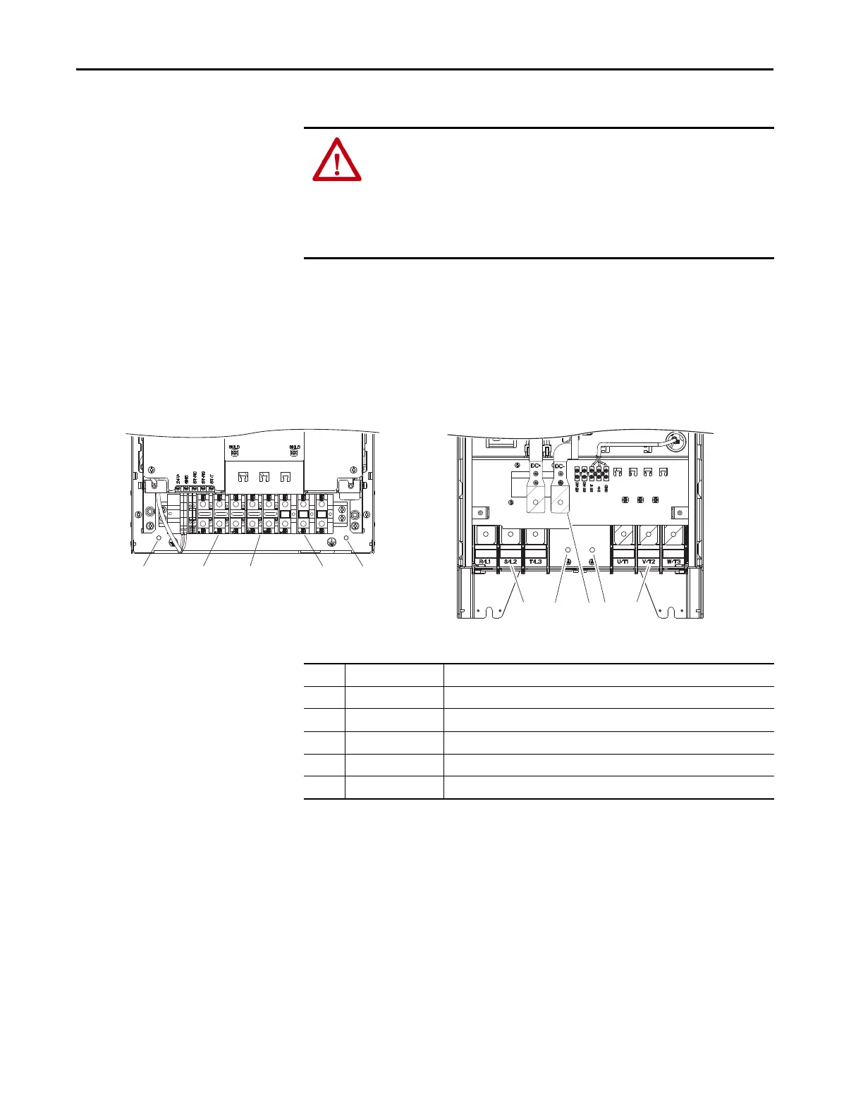
1 2 3 4 5
Item Name Description
1 PE grounding stud Termination point to chassis ground for AC line shield
2 R/L1, S/L2, T/L3 AC line input power terminals
3 DC+, DC– DC bus terminals
4 U/T1, V/T2, W/T3 AC output motor terminals
5 PE grounding stud Termination point to chassis ground for motor shield
 Loading...


