228 Rockwell Automation Publication 750-TG100B-EN-P - June 2019
Chapter 9 Power Bay Components
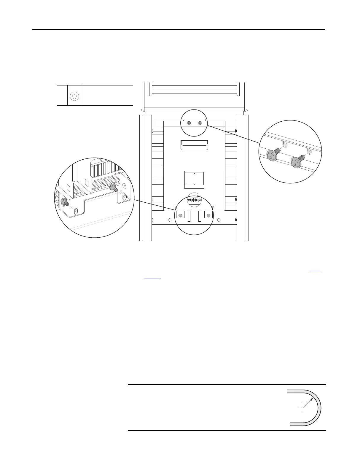
15. Remove the two M6 x 16 mm hex screws that secure the bottom of the
DC precharge module to the control bus support.
16. Remove the two M6 x 16 mm hex screws that secure the top of the DC
precharge module to the enclosure roof support bracket.
17. To remove the module by using the service cart and DC precharge module
lift, follow the detailed instructions in the PowerFlex 750-Series Service
Cart and DCPC Module Lift Installation Instructions, publication 750-
IN105.
18. Remove the module out of the enclosure.
Install the DC Precharge Module in the Enclosure
Install the DC precharge module into the enclosure in the reverse order of
removal.
When installing the fiber-optic cable:
1. Remove the transceiver from the fiber-optic port on the power layer
interface circuit board.
15,
16
M6 x 16 mm
T30
10.2 N•m (90 lb•in)
IMPORTANT
Minimum inside bend radius for fiber-optic cable is 50 mm
(2 in.). Any bends with a shorter inside radius can
permanently damage the fiber-optic cable. Signal
attenuation increases as inside bend radius is decreased.
 Loading...


