166 Rockwell Automation Publication 750-TG100B-EN-P - June 2019
Chapter 7 Control Bay and Control Pod Components
Install the Control Pod Fan Assembly
Install the control pod fan assembly in the reverse order of removal.
Control Pod Replacement
Replace the control pod assembly with kit catalog number
20-750-MCPOD1-F8M or 20-750-MCPOD2-F8M.
Remove the Control Pod
Follow these steps to remove the control pod.
1. Review the Product Advisories on page 14
.
2. Remove power from the system. See Remove Power from the System on
page 15
.
3. Open the control bay enclosure door.
4. Remove the control pod cover. See Control Pod Cover Removal on page
146
.
5. Remove the fiber-optic cables from the cable management devices in the
control pod.
6. Disconnect the AC precharge circuit board and torque accuracy module
fiber-optic cables from the ACP0 and ACPC1/TAM port on the fiber
transceiver board, respectively. Carefully coil the fiber-optic cable and
secure in a protected location. Follow the minimum bend radius
requirement.
7. For each line side inverter, disconnect the fiber-optic cable from the Ln
port on the fiber transceiver board. Carefully coil the fiber-optic cable and
secure in a protected location. Follow the minimum bend radius
requirement.
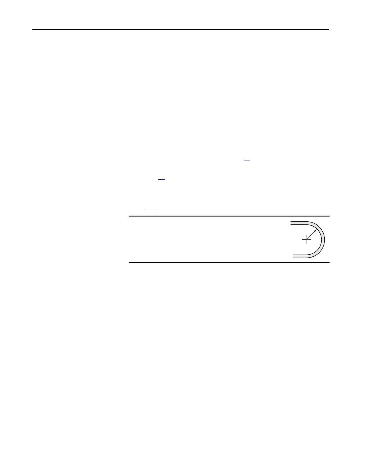
IMPORTANT
Minimum inside bend radius for fiber-optic cable is 50 mm
(2 in.). Any bends with a shorter inside radius can
permanently damage the fiber-optic cable. Signal
attenuation increases as inside bend radius is decreased.
 Loading...


