242 Rockwell Automation Publication 750-TG100B-EN-P - June 2019
Chapter 9 Power Bay Components
Remove the DC Link Fuses
Follow these steps to remove and replace the DC link fuses.
1. Review the Product Advisories on page 14
.
2. Remove power from the system. See Remove Power from the System on
page 15
.
3. Open the corresponding power bay enclosure door.
4. Remove the guards from the enclosure. See Guard Removal on page 235
.
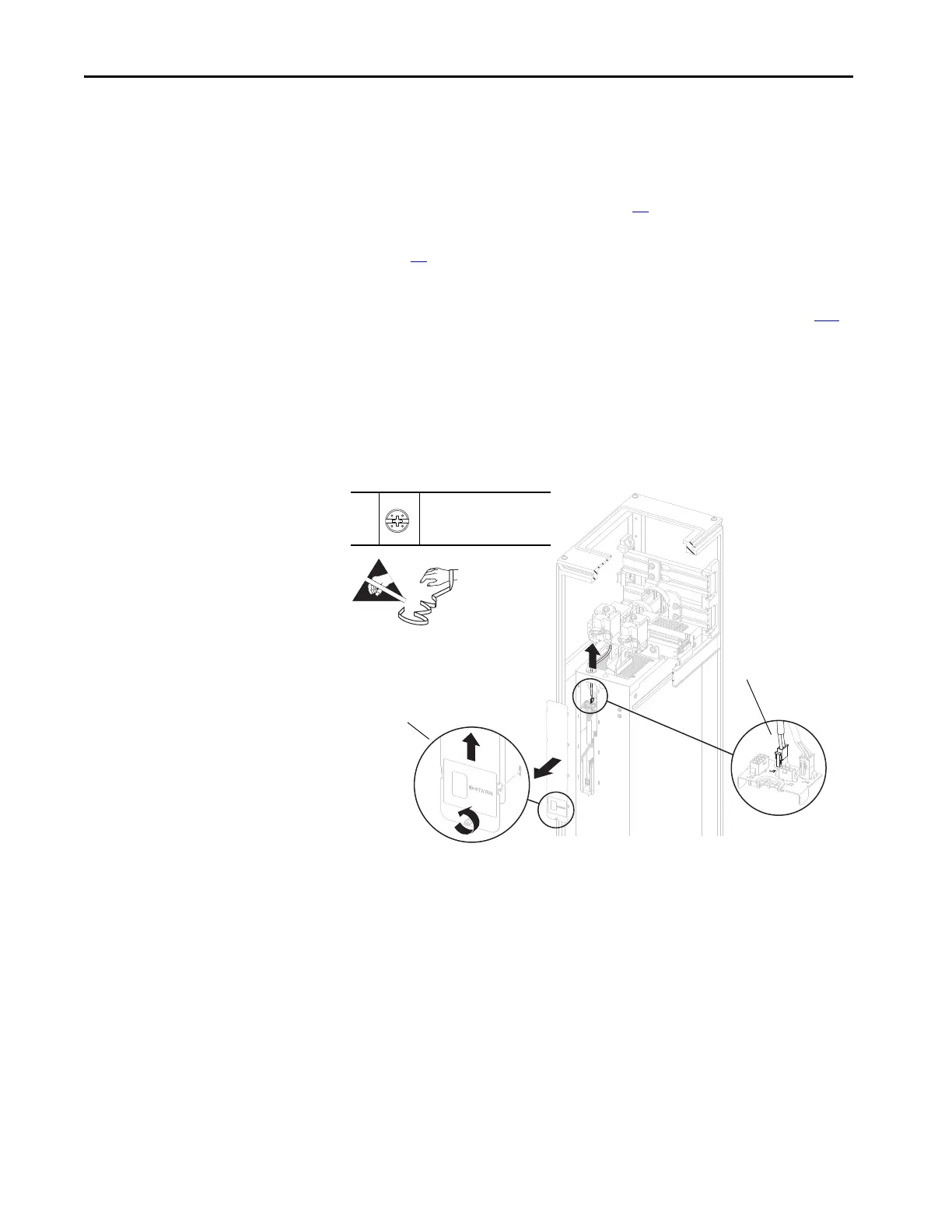
5. Loosen the thumb screw that secures the connections cover to the front of
the power module.
6. By using the screw, lift the connections cover up and off the power module
chassis.
7. Disconnect the cable connector P1 from connector J1 on the I/O panel in
the power module remove the cable from the power module chassis.
6
7
5
–
P2 or F - 6.4 mm (0.25 in.)
1.8 N
•m (16 lb•in)
 Loading...


