248 Rockwell Automation Publication 750-TG100B-EN-P - June 2019
Chapter 9 Power Bay Components
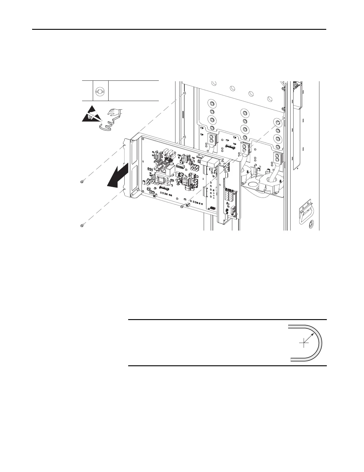
9. Remove the three M5 x 12 mm slotted-torx screws that secure the circuit
board tray to the power module chassis and, remove the tray by rotating
the left side away from the chassis and by sliding the tabs on the right side
of the tray out of the mounting slots.
Install the Circuit Board Tray
Install the circuit board tray in the reverse order of removal.
When installing the fiber-optic cables:
1. Remove the transceiver from the fiber-optic port on the circuit board.
2. Without bending the cable to a radius less than 50 mm (2 in.), fully insert
the fiber-optic cable into the transceiver.
3. Insert the transceiver and fiber-optic cable into the port on the board, until
you hear an audible ‘click.’
10
M5 x 12 mm
T25
6 N•m (53 lb•in)
IMPORTANT
Minimum inside bend radius for fiber-optic cable is 50 mm
(2 in.). Any bends with a shorter inside radius can
permanently damage the fiber-optic cable. Signal
attenuation increases as inside bend radius is decreased.
 Loading...


