Rockwell Automation Publication 750-TG100B-EN-P - June 2019 277
Power Bay Components Chapter 9
4. Remove the guard form the enclosure. See Guard Removal on page 235.
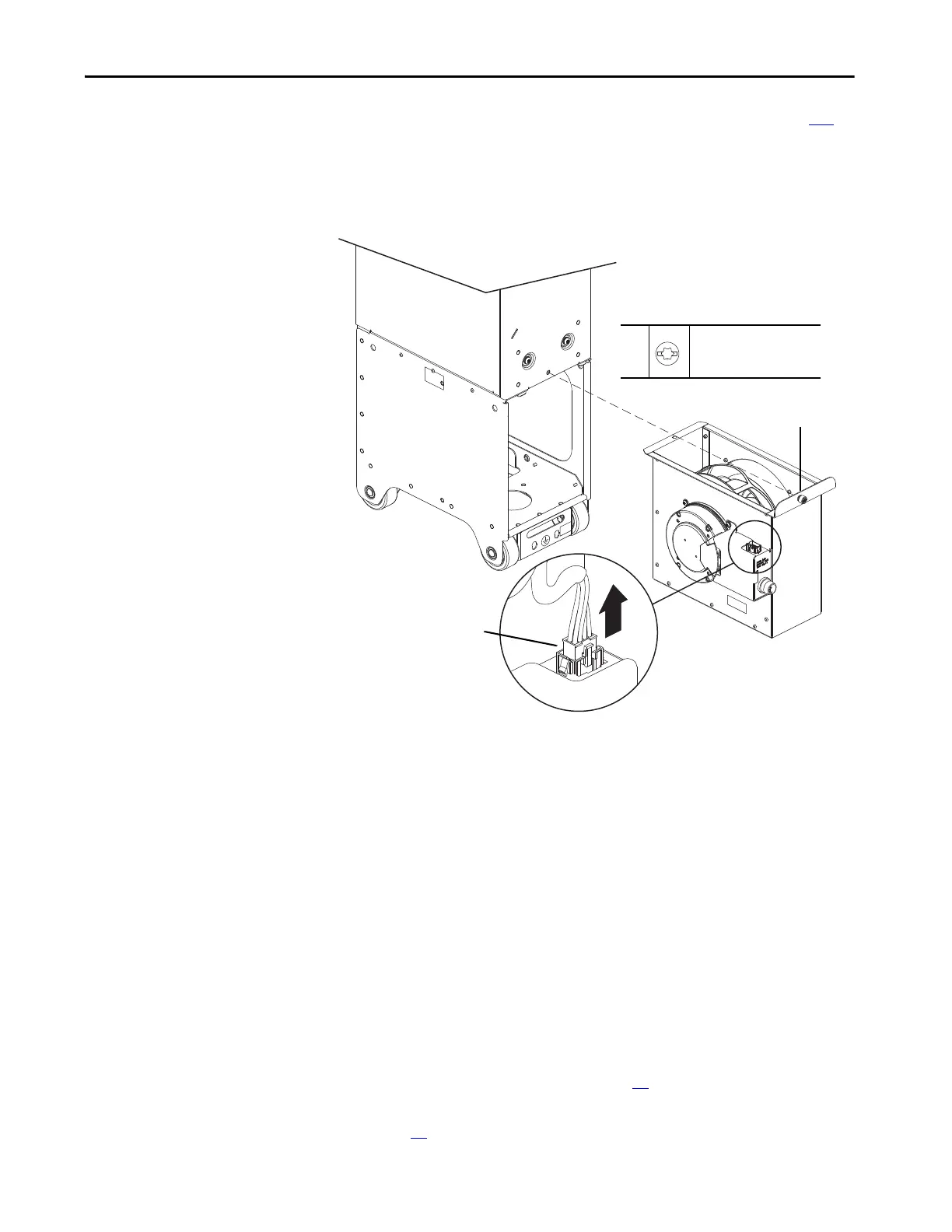
5. Disconnect connector P13 from connector J13 on the fan assembly
housing.
6. Loosen the M6 slotted-torx screw that secures the fan housing to the
power module chassis and slide the fan assembly out of the chassis.
Install the Power or LCL Filter Module Heatsink Fan Assembly
Install the power or LCL filter module heatsink fan assembly in the reverse order
of removal.
Torque Accuracy Module
Replacement
Replace the torque accuracy module with the appropriate kit catalog number:
• 20-750-MTAM1-CD (400/480V)
• 20-750-MTAM1-EF (600/690V)
Remove the Torque Accuracy Module
Follow these steps to remove and replace the torque accuracy module.
1. Review the Product Advisories on page 14
.
2. Remove power from the system. See Remove Power from the System on
page 15
.
6
M6
T30
2.6 N•m (23 lb•in)
5
6
 Loading...


